BeneVision N Series Patient Monitor Operator’s Manual 2 - 9
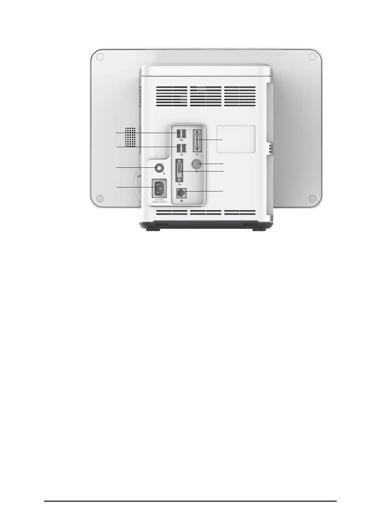
2.3.3.4 N15, N12, N12C Rear View
(1) USB connectors
Connect USB devices, for example the keyboard, mouse, and barcode reader.
(2) Equipotential Grounding Terminal
When using the monitor together with other devices, connect their equipotential grounding terminals together
to eliminate the potential difference between them.
(3) AC Power input
(4) Satellite module rack connector
For N15, connects the SMR and N1 or T1 Dock.
For N12/N12C, connect N1 or T1 Dock.
(5) Nurse call connector
It is a BNC connector. It connects the monitor to the hospital’s nurse call system through the nurse call cable (PN:
8000-21-10361). Alarms from the monitor are sent to the nurse station through the nurse call system, if
configured to do so.
(6) Digital video connector: connects external display.
(7) N
etwork Connector
It is a standard RJ45 connector which connects the monitor to the central monitoring system (CMS) or other
network devices.
 Loading...