7 - 14
7.6 Grounding Extension Units
7.6.1 Wiring FG cable of bus connection cable
(1) When using GT15-C EXSS-1
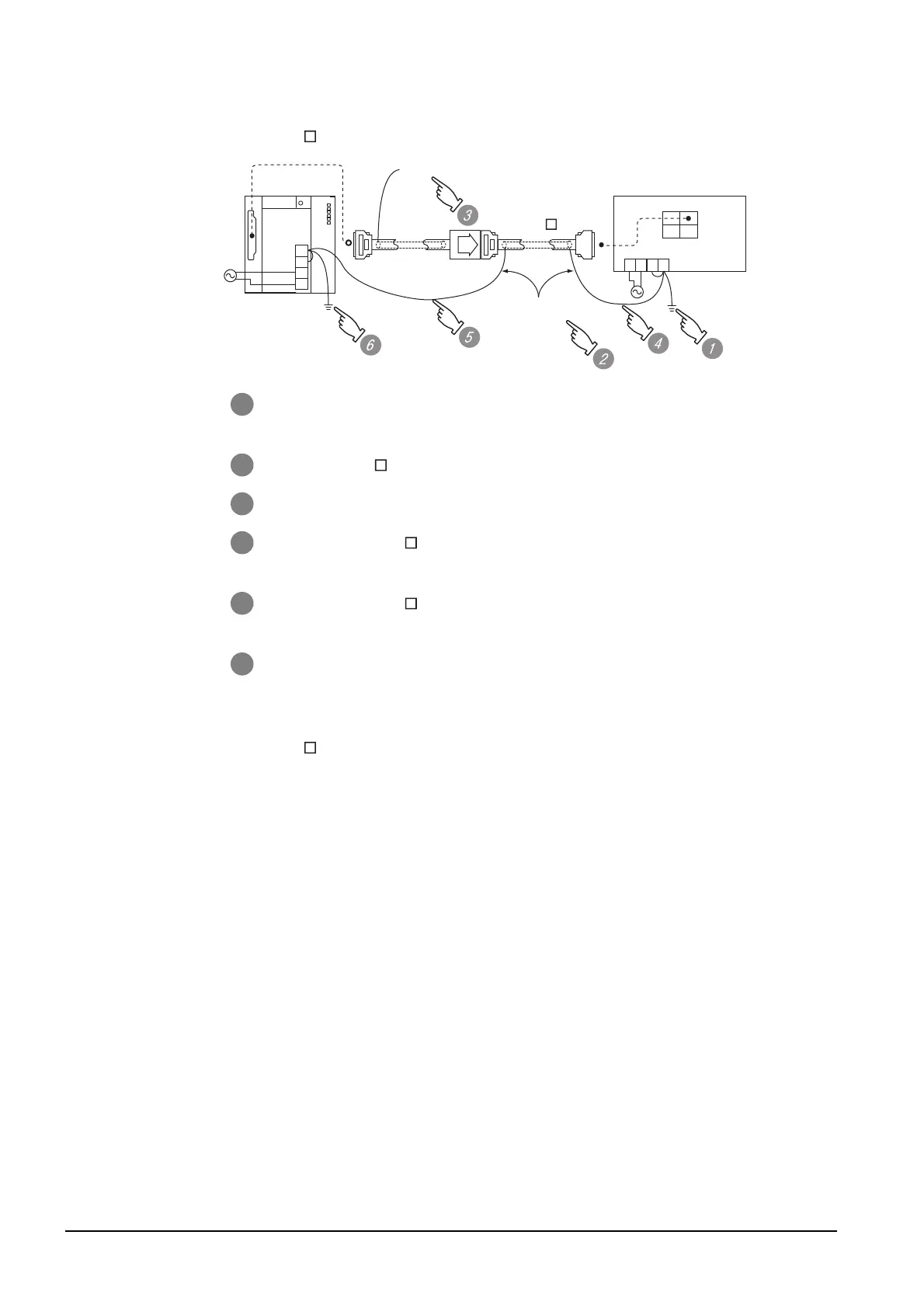
(2) When using GT15-C BS
For the both side GOTs, connect the LG and FG terminals of the terminal block on the GOT unit
power and ground them with a cable.
1 Connect the LG and FG terminals of the terminal block on the GOT unit power
and ground them with a cable.
2 Use the GT15-C BS's FG cable of 28cm or less.
3 Do not connect the GT15-EXCNB's FG ground cable.
4 Connect the GT15-C BS's FG cable on the GOT side to FG of the GOT unit
power's terminal block.
5 Connect the GT15-C BS's FG cable on the PLC side to FG of the PLC's
power supply module.
6 Connect the LG and FG terminals of the terminal block on the PLC and ground
them with a cable.
FG
LG
N
L
PLC
Not connected
(GT15-EXCNB)
GOT
OUT IN
FGLG
NL
2SQ cables to
FG terminals,
28cm or less
(GT15-C BS)

 Loading...

