8 - 16
8.1 Communication Unit
8.1.3 Installing multiple extension units in layers
4 When installing another extension unit on the unit that has been installed, implement the above
operations of to .
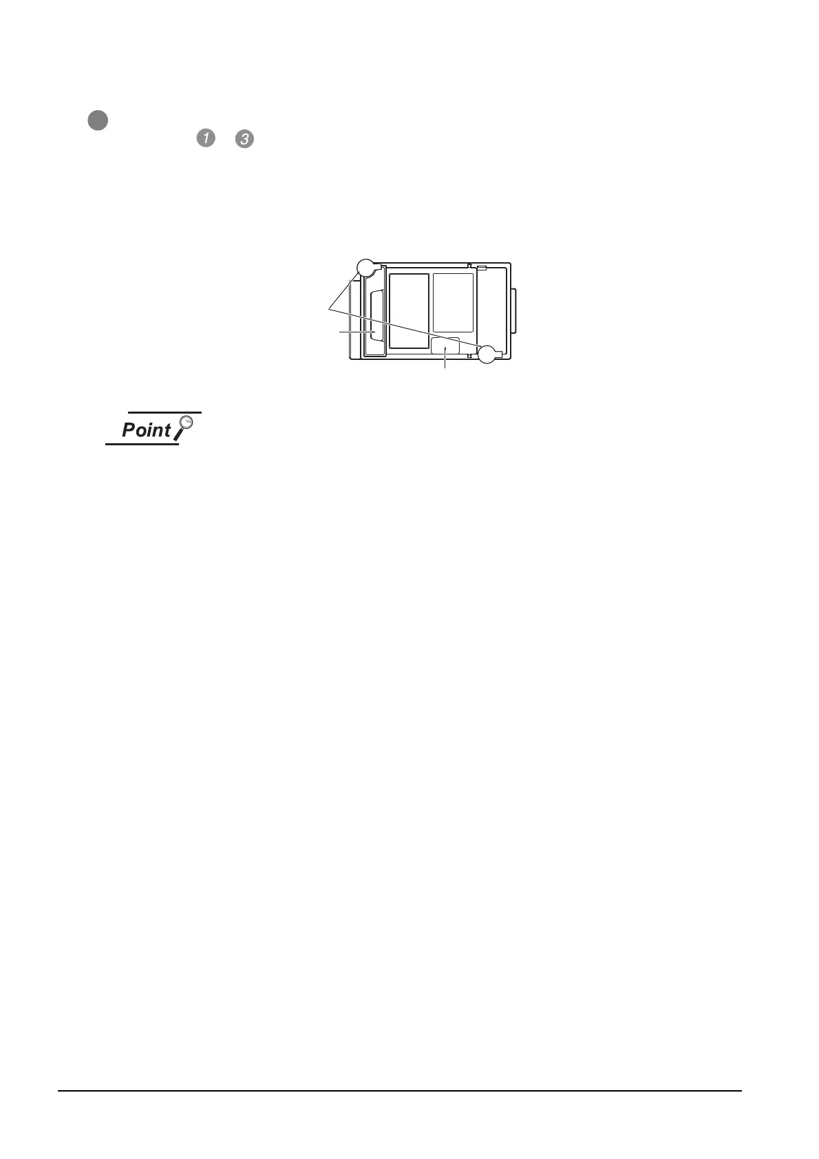
5 When not installing an extension unit on the unit that has been installed, in order to avoid receiving
electrostatic, stick accessory stickers to cover the top of mounting screws.
6 Keep the connector cover fixed.
7 Keep the sticker stuck as it is.
8
(1) Installation position for a communication unit that occupies two extend I/Fs
Install a communication unit that occupies two extend I/Fs directly to the GOT
main unit.
It cannot be installed on the back stage of another communication unit.
If a video/RGB unit has been installed, install the communication unit on the back
stage of that video/RGB unit.
(2) Installing the GT15-75QBUSL, GT15-75QBUS2L, GT15-75ABUSL, GT15-
75ABUS2L
These cannot be installed on the back stage of a video/RGB unit. For bus
connection, use the GT15-QBUS, GT15-QBUS2, GT15-ABUS, or GT15-ABUS2.
(3) Removing video/RGB unit, bus connection unit (GT15-QBUS2, GT15-ABUS2),
MELSECNET/H communication unit, CC-Link IE Controller Network
communication unit, CC-Link IE Field Network communication unit, CC-Link
communication unit (GT15-J61BT13)
Before removing the unit, unscrew the extend interface board fixing screws.)
Sticker
ccessory
stickers
Connector
cover

 Loading...

