8.4 Video/RGB Unit
8.4.2 Installing procedure
8 - 23
1
OVERVIEW
2
SYSTEM
CONFIGURATION
3
SPECIFICATIONS
4
PART NAME AND
SETTINGS
5
EMC AND LOW
VOLTAGE
DIRECTIVE
6
INSTALLATION
7
WIRING
8
OPTION
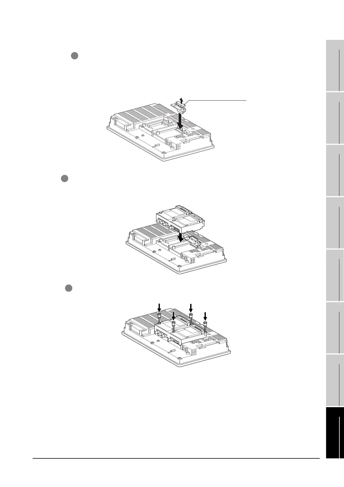
5 After the installation, tighten the mounting screws (4 places) in the specified torque range (0.36
to 0.48N·m).
3 Install the extend interface relay board on the Extend I/F-2 side of the GOT.
After the installation, detach the connector cover from the extend interface relay board.
Remove the connector cover
4 Install the video/RGB unit on the extension interface of the GOT rear face.
(When the extension unit is installed in GOT, remove the installed extension unit. And, do not
touch the board in the GOT when install the video/RGB unit.)

 Loading...

