4.3 Part Names and Settings of the GT157
4 - 7
1
OVERVIEW
2
SYSTEM
CONFIGURATION
3
SPECIFICATIONS
4
PART NAME AND
SETTINGS
5
EMC AND LOW
VOLTAGE
DIRECTIVE
6
INSTALLATION
7
WIRING
8
OPTION
*1 It is provided for the GT1575V-S only.
*2 For the multi-color display board, refer to the following.
3.2.3 GT1575V-S, GT1575-S, GT1575-V, GT1575-VN, GT1572-VN
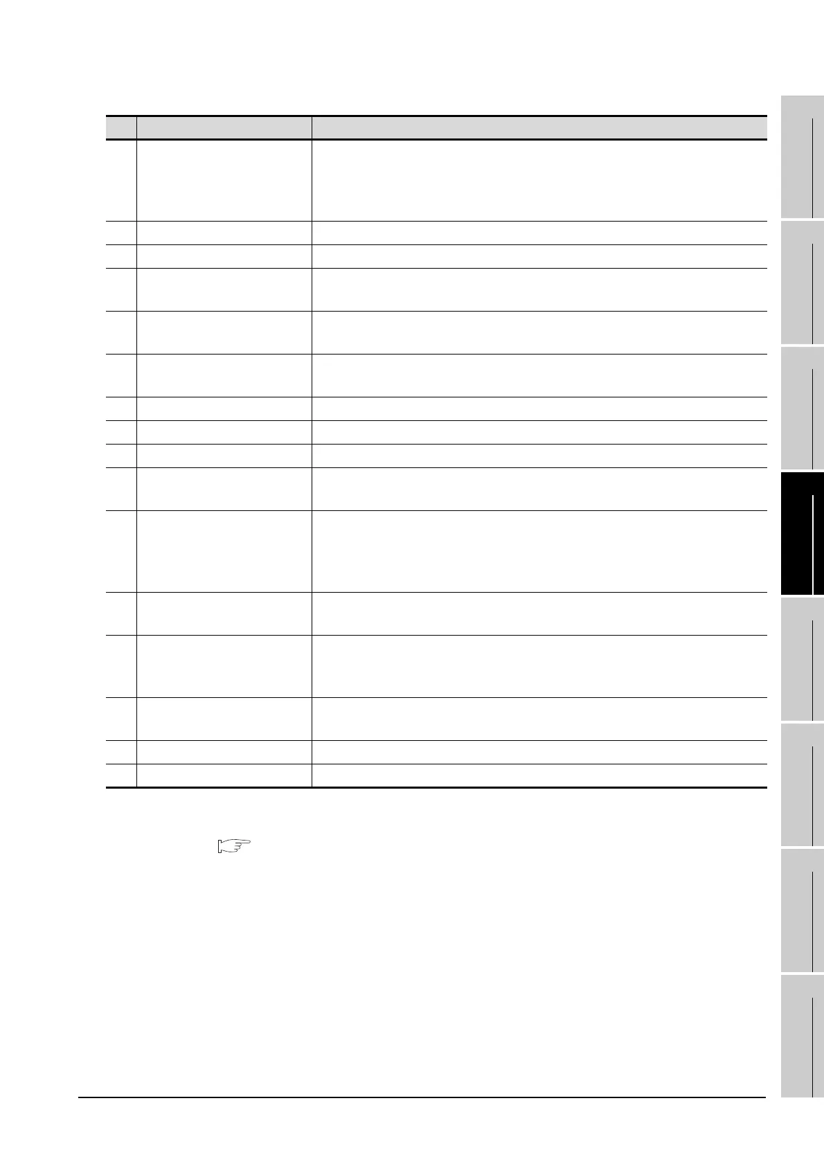
No. Name Description
1) POWER LED
Lit in green : Power is correctly supplied
Lit in orange : Screen saving
Blinks in orange/green : Blown back light bulb
Not lit : Power is not supplied
2) Display screen Displays the utility and the user creation screen.
3) Touch key For operating the touch switches in the utility and the user creation screen
4)
Video/RGB interface
*1
For installing the video input unit, RGB input unit, video/RGB input unit, or RGB
output unit
5) USB interface
For connecting a personal computer
(Connector type: TYPE Mini-B)
6) RS-232 interface
For communicating with a controller or connecting a personal computer
(Connector type: D sub 9-pin)
7) Power terminal Power input terminal, LG terminal, FG terminal
8) Extension interface For installing an extension unit
9) CF card interface For installing a CF card
10) CF card access LED
Lit : CF card accessed
Not lit : CF card not accessed
11) CF card access switch
Used for stopping the access to the CF card before removing the CF card from the
GOT
ON : CF card being accessed (CF card removal prohibited)
OFF : CF card not accessed (CF card removal possible)
12)
Optional function board
interface
For installing the optional function board
13)
Multi-color display board
interface
*2
For installing the multi-color display board
(For GT1575-VN and GT1572-VN, 65536 color display is not supported even with
the multi-color display board installed.)
14) Reset switch
Hardware reset switch
(Inoperative in the bus connection or with the bus connection unit installed)
15) Hole for unit installation fitting Hole for inserting the unit installation fitting
16) Battery holder Houses the battery.

 Loading...

