MC2000 – Assembly Instruction Manual
10
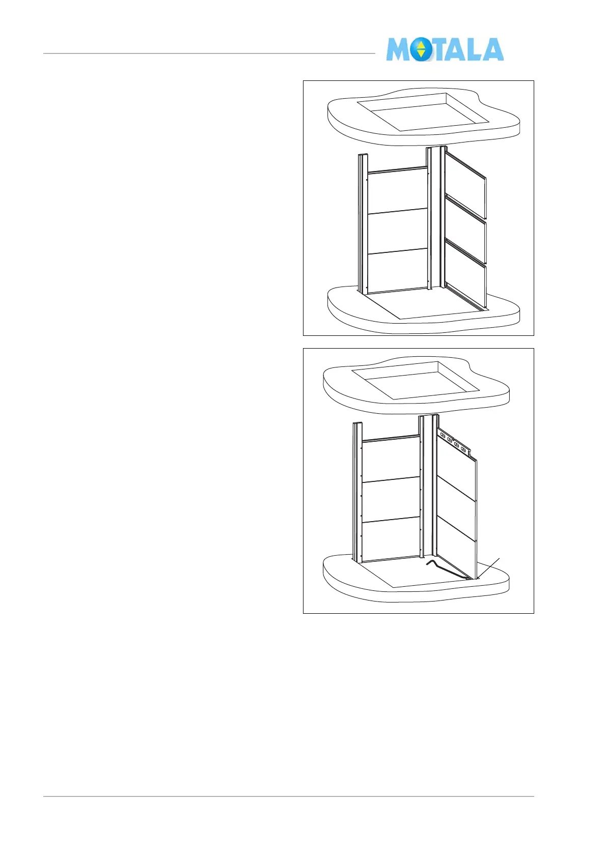
10. Place a U-profile (25 mm) under the lift well
module/glass module on side D. Turn the
notch of the U-profile towards the outside
of the lift well.
11. Place three lift well modules/glass modules
on si
de D. Turn the “male side” upwards.
The modules must not reach the very bot-
tom of the corner profiles. Leave a millime-
tre or two so that, later, you will be able to
al
ign the whole side C vertically.
12. Fasten the modules in the corner profile by
f
astening one screw at the top and one at
the bottom about 100 mm from the edges.
Note! The screw heads in the corner profile
of the driving side must be placed at least 6
mm from the corner profile to leave room
for the guide rail flange.
13. Align horizontally by means of a spirit-level.
14. If necessary, use metal shims.