MC2000 – Assembly Instruction Manual
24
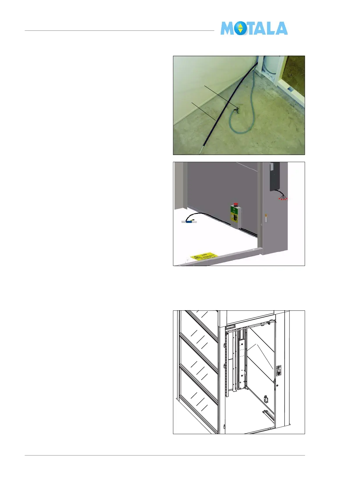
Landing 0, pit
Guide rails
Lower guide rails
1. Pull the cable with terminal block “control
p
anel - terminal block pit” through the
opening in the door frame. (Length of cable
to the block approx. 0.8 m.)
2. Pull the door lock wire through the same
open
ing.
3. Install “terminal block with the stop button”
and cabe
l for the pit prop and end limit
switch 62:U on the side wall of the driving
side in the lift well. It should be placed in a
position of 100mm from centre nearest
door side, about 50 mm upwards on the
wall.
4. Route the cable for the pit prop into the cor-
ner profile and out where the recess for the
pi
t prop is. The end limit and the pit prop
shall be fitted later.
1. Place the lower rails in the lift well. Note the
markings A and C. Side A is always the
side where the motor and the gear are
placed.