37
MC2000 – Assembly Instruction Manual
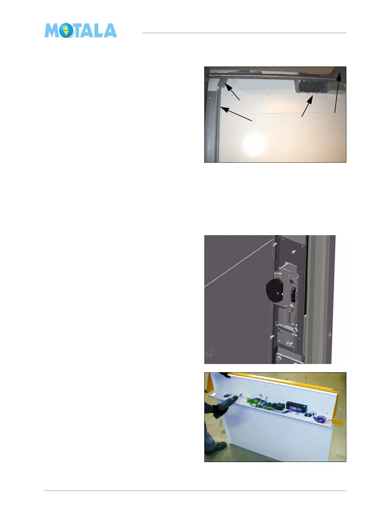
Travelling flex cable, panel plate, overload unit and control panel
1. Run the lift to the topmost landing.
2. Lower the flex cable (1) with the platform
te
rminals in the end on the opposite side of
the door on floor 0. The unpeeled part of
the cable should reach the pit precisely.
Lower the cable another 1150 mm.
3. Secure the travelling cable with U-fasten-
ers (2).
4. Fasten the remaining parts of the travelling
cabl
e with U-fasteners. The cable must not
run down further than 180 mm from the
well top. Check that no cables can touch
the driving shaft. Note! If the lift has an
electrical emergency lowering device (3).
Also leave place for that.
5. Install the protection over the safety gear
(4
).
6. Fit (if any) the electrical emergency lower-
ing device. Route the cables 28 and 29 to
th
e control panel.
7. Switch off the supply voltage of the lift,
ro
ute and connect the travelling cable to
block X1 in the control panel.
8. Switch on the supply voltage of the lift,
dr
ive down to landing 0 and switch off the
power.
9. Fit the retiring ramp on the same side as
th
e motor is fitted. A-side.
10. Attach the panel shelf with electric equip-
ment on the panel plate of the platform.