7
MC2000 – Assembly Instruction Manual
Assembly
Introduction
General information on how to erect modules
Lift well modules
Glass modules
Construction of precision gauge blocks
This section contains general information on
how t
o construct so called precision gauge
blocks and how to erect lift well modules and
glass modules.
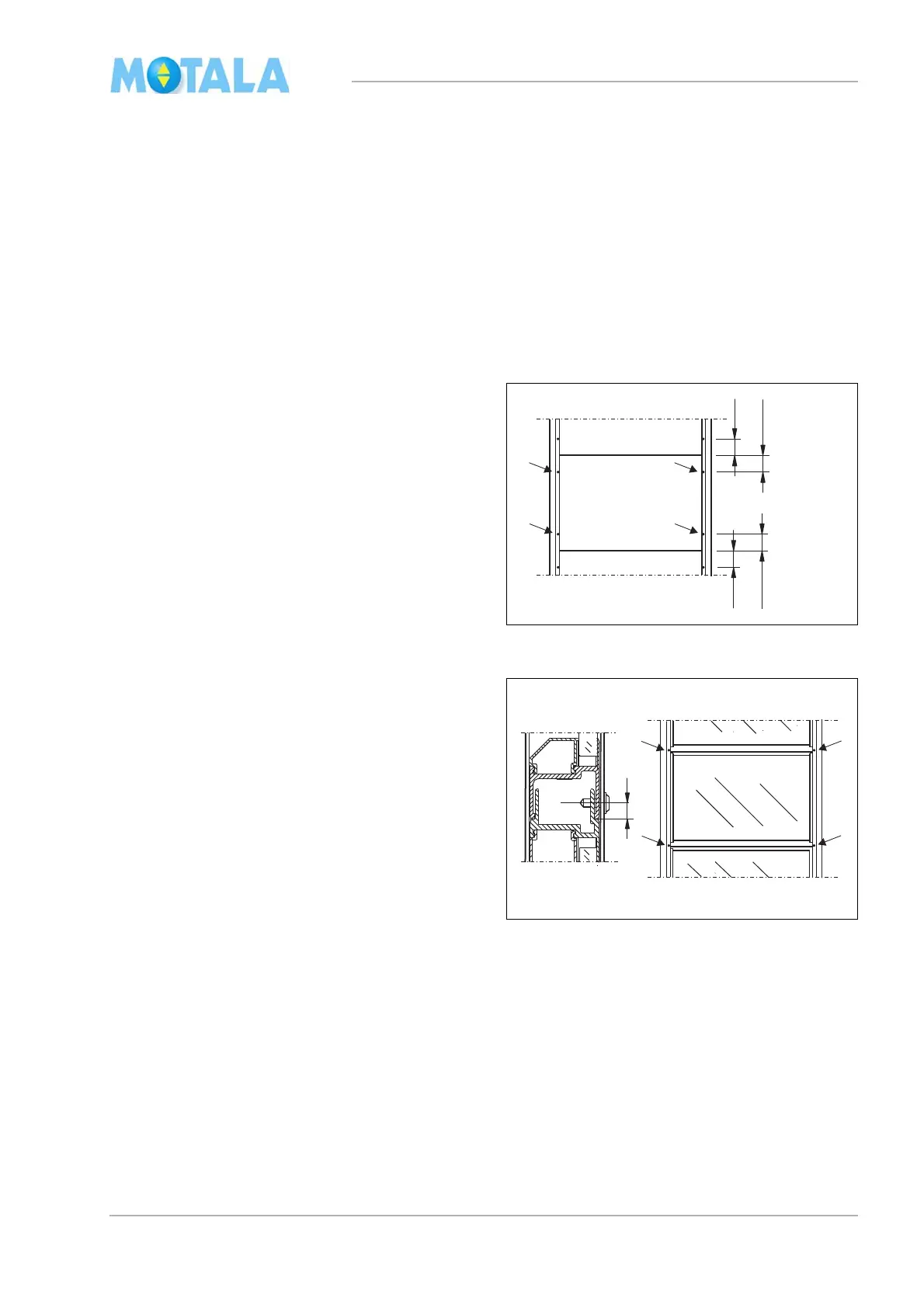
Generally, each module is assembled with four
scr
ews in the corner profiles. The screws are
placed about 100 mm from the upper and lower
edges.
For a nicer look, the screws can be exchanged
by
pop rivets (4 mm).
Glass modules are to be placed with the bevel-
led window moulding on the outside of the lift
well
. (The flush side on the inside.)
The modules are generally put together so that
each modul
e is fastened with four screws in the
corner profiles. You need to pre-drill 3,2mm.
The screws in the splice between two modules
are
placed about 8 mm from the lower edge of
the upper module so that the screw also goes
through the male profile of the lower module.
For glass modules, precision gauge blocks are
used at joist passages and in the pit so that the
glass surfaces are placed at the proper height
according to the layout drawing. Note that the
measurements in the layout drawing apply to
cutting measurements of the precision gauge
blocks. Example: see the heading “Layout
drawing” on page 48