9
MC2000 – Assembly Instruction Manual
Lift well assembly according to
layout drawing.
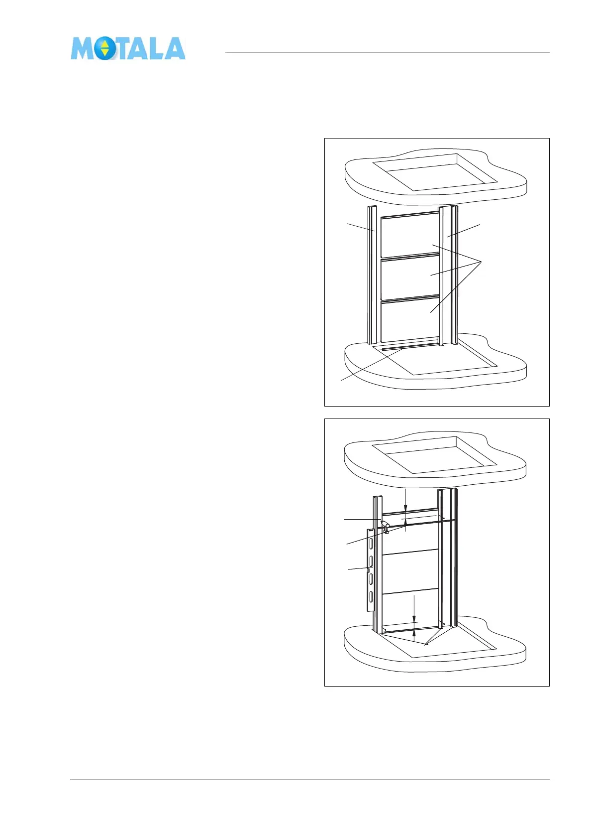
Bottom part of the lift well, landing 0
1. Erect the broad corner profile on side C of
the lift well. Note that the broad profile must
be placed against side D.
2. Erect the thin corner profile.
3. Place a U-profile (35 mm) on the bottom
si
de, “female side”, at the bottom of the
lowest lift well module/glass module. The
notches (ends) of the U-profile should be
turned towards the outside of the lift well.
4. Place three lift well modules/glass modules
bet
ween the corner profiles. Turn the “male
side” upwards. The modules must not
reach the very bottom of the corner pro-
files. Leave a millimetre or two so that,
l
ater, you will be able to align the whole
side C vertically.
5. Place a short dimension stick between the
cor
ner profiles. Check that the base is
level.
6. If necessary, adjust with a metal shim un-
der the corner profiles. The shim must be
pl
aced under the corner profile and the
module. Note! When plumbing, always
start at the “highest point” of the pit.
7. Fasten the modules in the corner profile by
at
taching one screw at the top and one at
the bottom of each side about 100 mm
from the edges. Use a dimension stick.
(For placing of screws, see the heading
“General information on module assembly”
on page 7).
8. Align vertically by means of a long spirit-
le
vel.
9. Fasten the modules and the corner profiles
wi
th screws.