27
MC2000 – Assembly Instruction Manual
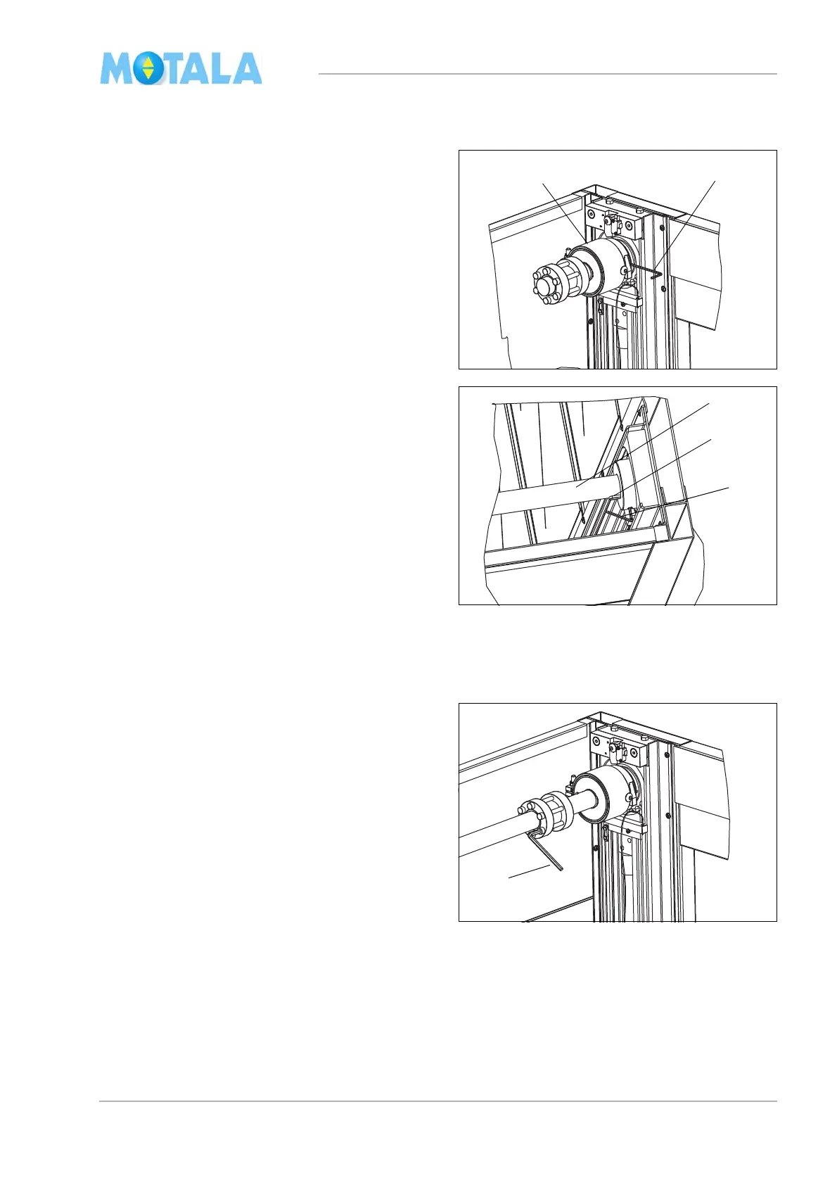
Driving shafts, gear and motor
1. Carefully push the safety gear shaft into the
sprocket wheel on side A of the lift. Note!
Do not use force!
2. Fasten the lock screw (use a 3 mm socket
wren
ch).
3. Carefully insert the long driving shaft into
si
de A. Check that the shaft reaches the
very bottom of the sprocket wheel bearing
in the turning case. Maximally 20 mm of the
keyway should be seen. Note! Do not use
force!
4. Fasten the lock screw (use a 4 mm socket
wren
ch.)
5. Loosen the four M10 screws (transport po-
sition) on each slide so that the shafts can
be tur
ned by hand. (Note! These screws
will be needed later for platform fitting.)
6. Measure and adjust the chain joints of the
two gui
de rails so that they are at the same
distance from the turning case.
7. Pull the shaft coupling tight crosswise (use
a
6 mm socket wrench 41 Nm).