29
MC2000 – Assembly Instruction Manual
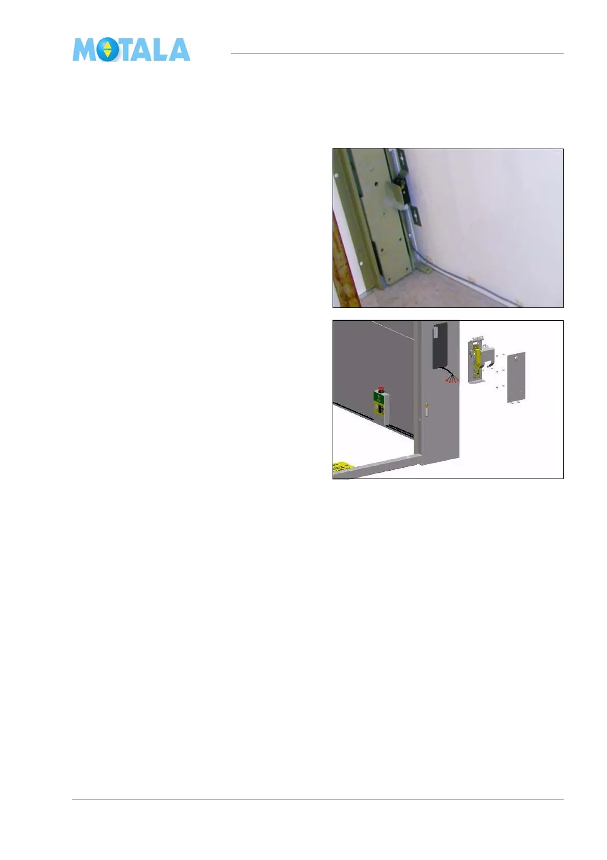
Connecting pit functions
Connect the cables according to the electrical
diagram of the lift. The bottom floor is called
“landing 0” in the diagram.
1. Fit temporarily and connect the terminal
fl
oor switch (marked with an arrow in the il-
lustration). The friction roller should be
pl
aced at least 40 mm from the outer edge
of the guide rail. (The position is to be ad-
justed later).
2. Fit and connect the pit prop, contact 155:1
and the
position contact 155:2. See in the
electrical drawings
3. Fasten all cables in the side wall of the lift
wel
l.
4. Fit the pit prop cover.