11
MC2000 – Assembly Instruction Manual
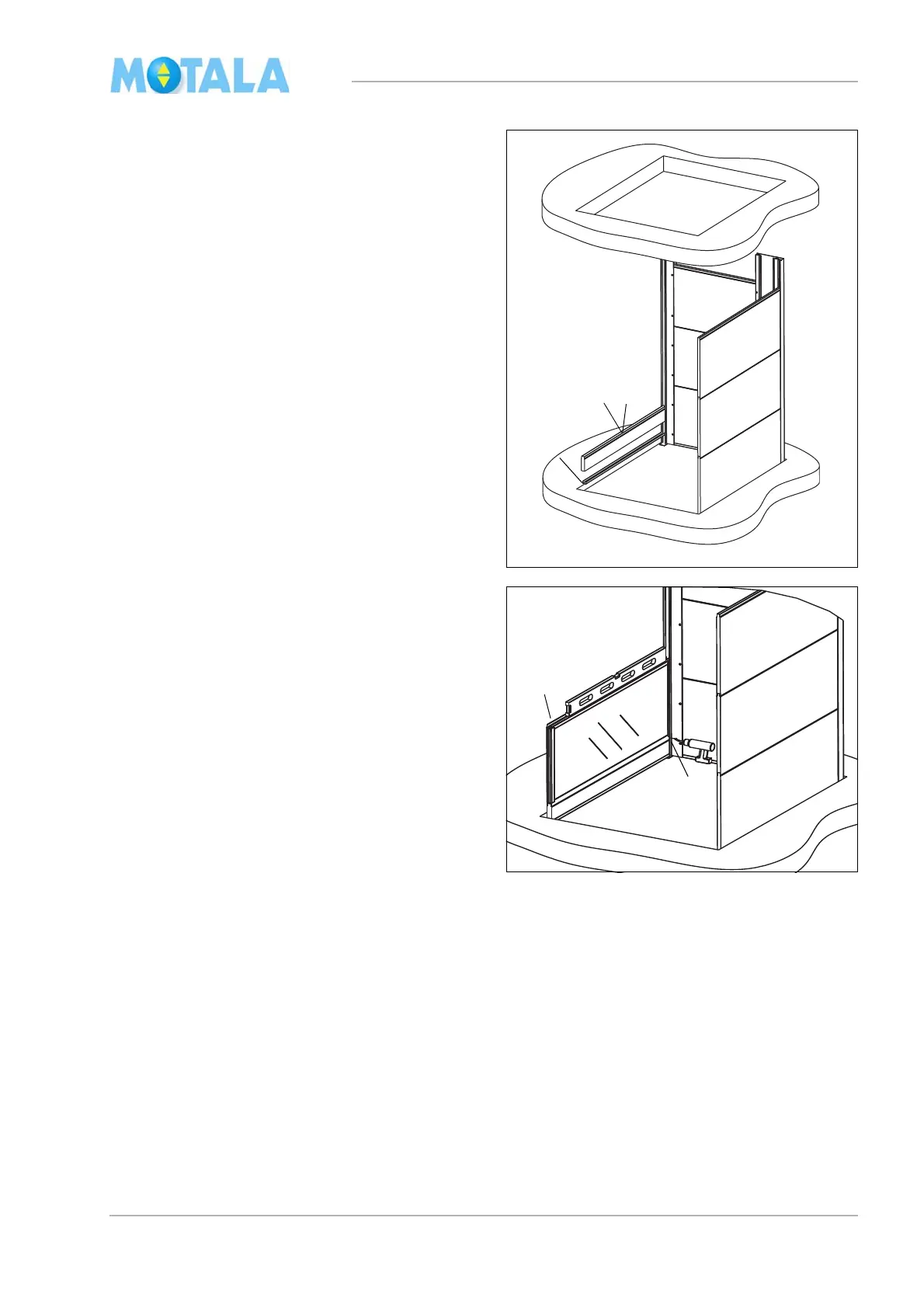
In this example, the lift well side B has glass
modules. The first glass module must not be in
close contact with the pit but should be placed
a little higher up. For measurments, see the lay-
out drawing.
15. Using the male section of a lift well module,
cons
truct a precision gauge block and
place it in close contact with the pit. See
the heading “Construction of precision
gauge blocks” on page 7.
16. Install the U-profile with the notch turned
to
wards the outside of the lift well.
17. Fit the precision gauge block.
18. Place a glass module on top of the preci-
sion gauge block. Turn the “male side” up-
wards and the level glass side towards the
l
ift well. Check with a spirit-level that the
upper edge of the glass module is horizon-
tal.
19. If necessary, adjust with a metal shim be-
tween the precision gauge block and the
pi
t.
20. Fasten the glass module with a screw in
th
e longitudinal bottom corner profile. See
the heading “Glass module” on page 7.