MC2000 – Assembly Instruction Manual
40
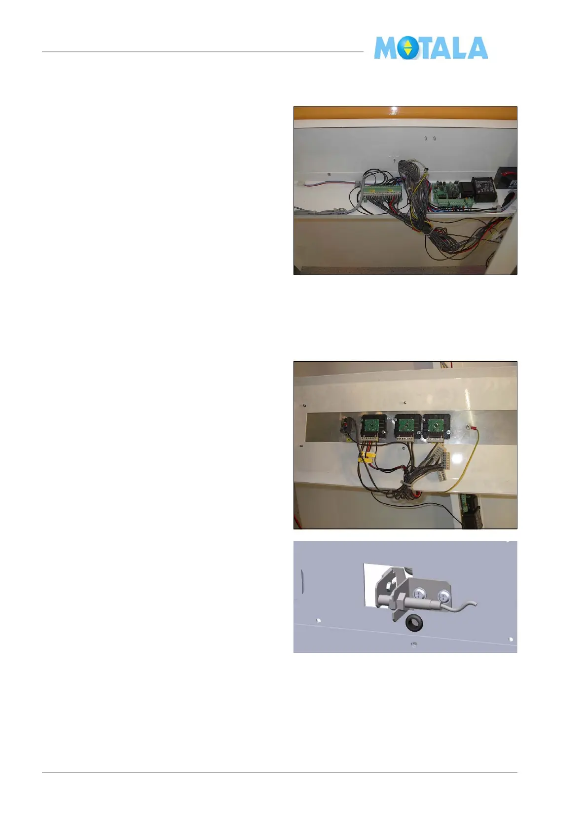
Electric connections on the platform panel
plate
All electric connections are made according to
th
e electrical diagram of the lift. Fasten all ca-
bles from the slide to the panel shelf on the in-
side of the angle bracket with cable tie (not on
th
e top or bottom sides).
1. Connect the following cables:
• the travelling cable 51.
• the cable from the floor sensitve edge con-
tacts 57.
• the cable from the sensitive edge of the
p
anel plate 56.
• the cables 62-65 from the high speed con-
tact 66:, 59:, 51: and intermediate floor
det
ector 61:, if any.
• the cable 53 from the retiring ramp.
2. Connect alarm and telephone equipment, if
any
. Do not yet install the battery, as the
alarm signal might ring.
3. Push in both the stopbutton on the control
p
anel and the commission box.
4. Connect the control panel.
5. Connect the battery. Im
portant! If the lift
has the electrical emergency lowering
system as an option. The battery on the
panel is replaced with the battery in the
emergency lowering unit, suited at the
top of the shaft. You shall not in any cir-
cumstances connect two batteries!
6. Switch on the main power
7. Bring in test load on the platform.
8. Adjust by move the transmitter in or out-
wards. The transmitter shall light when it’s
act
ivated. Also check that input 0 on the
PLC lights up. Note. Do not tighten the
nuts to hard you may damaged the trans-
mitter.