6 Functions and settings
Maschinenfabrik Reinhausen 201460 2374092/04 ENTAPCON® 260
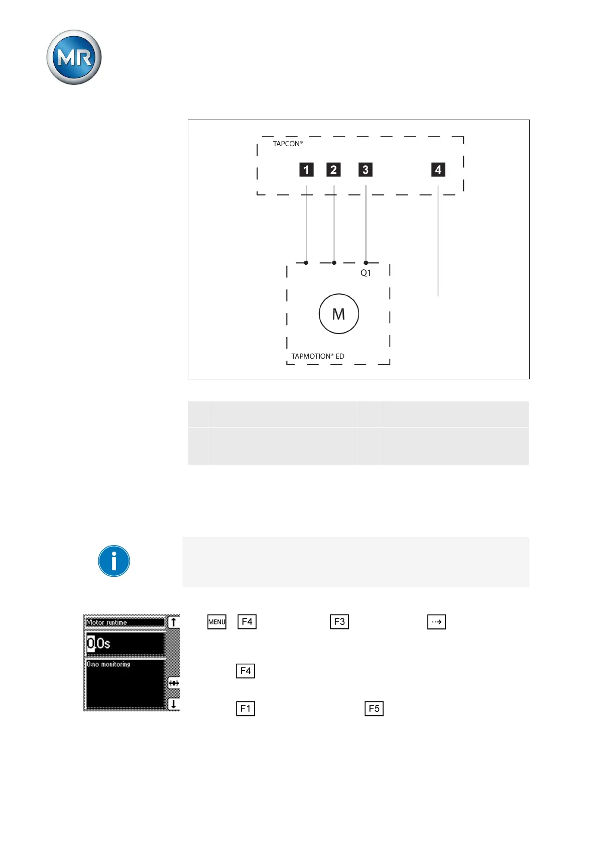
Figure 41: Wiring for motor runtime monitoring
1 Motor running control input
I/O
3 Motor protective switch output
relay I/O (optional)
2 Motor protective switch trig-
gered control input I/O (op-
tional)
4 Motor-drive unit runtime ex-
ceeded output relay I/O (op-
tional)
If you want to use the output relay, the feedback from the motor-drive unit
Motor protective switch triggered must also be wired to a control input and
parameterized. This message resets the Motor runtime exceeded output re-
lay when the motor protective switch is switched back on and activates the
Motor protective switch triggered message.
If the runtime monitoring is set to 0.0 seconds this equates to it being
switched off.
To set the motor runtime, proceed as follows:
1. > Configuration > General > Press until the desired
parameter is displayed.
ð Motor runtime.
2. Press to highlight the position.
ð The desired position is highlighted and the value can be changed.
3. Press to increase the value or to reduce it.