6 Functions and settings
Maschinenfabrik Reinhausen 201480 2374092/04 ENTAPCON® 260
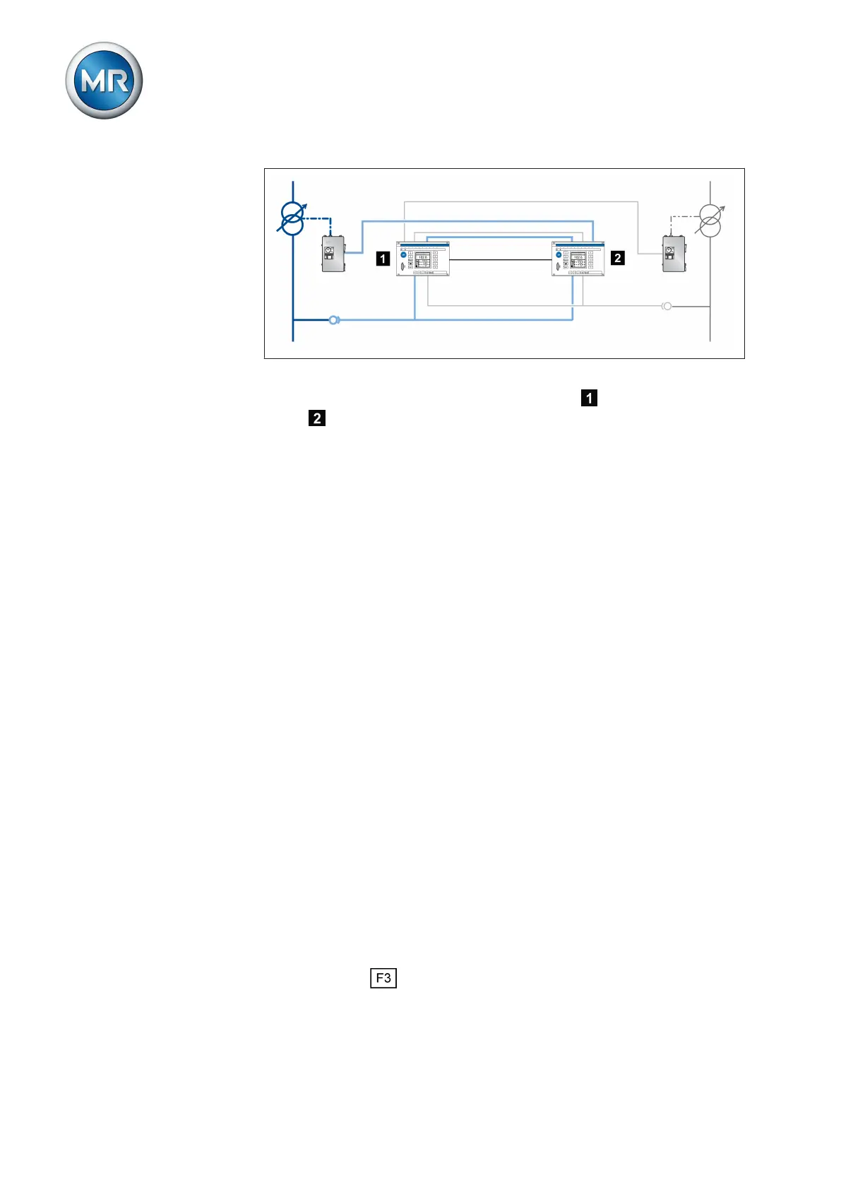
Figure 50: Cross-monitoring
For the check, the measured voltage of the device is transmitted to the
device via a second separate measurement input and vice versa. The
calculated measured voltage is compared with the original measured values
via the CAN bus. If the measured values deviate, the Measured value error
message is issued.
When checking the limit values, one device transmits a measured voltage to
the other via the second separate measurement input. You can set the fol-
lowing limit values for this measured value:
▪ Separate desired value [► 80]
▪ Undervoltage limit value [► 81]
▪ Overvoltage limit value [► 82]
As soon as one of the set limit values is exceeded, once the set delay time
for the error message [► 83] has lapsed, the Measured value error mes-
sage is output. If wired accordingly, relay contacts can block the raise/lower
pulse to the motor-drive unit. Regulation of individual devices is not affected
by limit value monitoring.
The following sections describe how you set the relevant parameters for the
monitoring device.
Also refer to
2 Setting delay time for error message [► 83]
2 Setting desired value for regulator 2 [► 80]
2 Setting undervoltage limit value V< for regulator 2 [► 81]
2 Setting overvoltage limit value V> for regulator 2 [► 82]
Setting desired value for regulator 2
You can use this parameter to set the desired value for the device to be
monitored.
You can use the key to change the display to the following units:
No measured value or
measurement card error
Checking the limit values
6.8.1