Training Guide Course No. 196514
Level 2 Maintenance, X-1000 Series Dispensing Systems 4-26 P/N 196515 (Revision A)
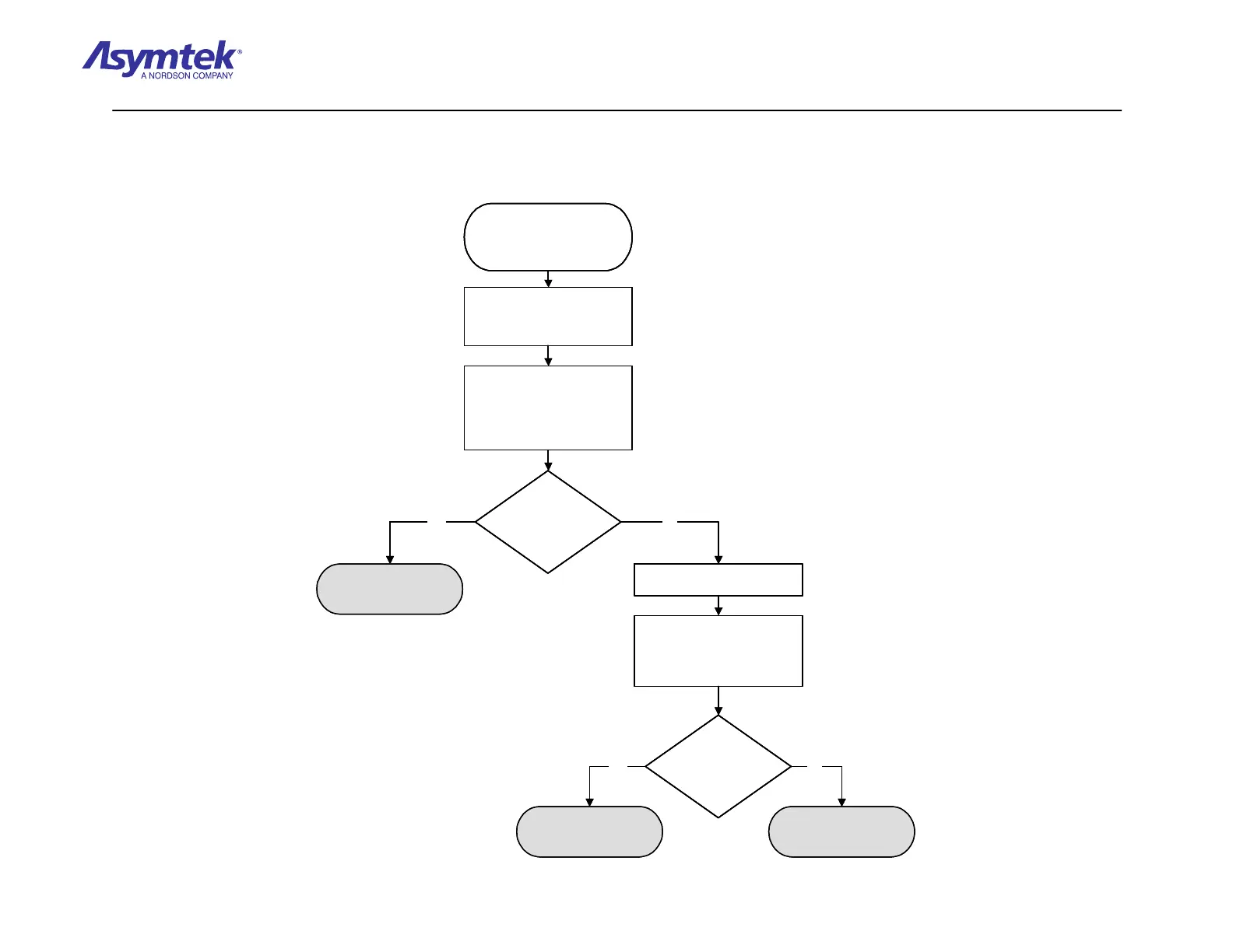
Verify the Signals Cable is
connected to J7 on the XY Servo
Interface PWA and J5 on the X
Servo Amplifier PWA.
Is the reading greater
than 4 VDC?
Signals Cable (P/N 06-
0403-00) is root cause of
Servo Low Power fault.
With Front Hatch closed,
measure the VDC at Pin 3,
Jumper J1 on X and Y Servo
Amplifier PWAs. Use TP8 labeled
GND on XY Servo Interface
PWA for ground.
Locate chip U3 on XY Servo
Interface PWA.
With the Front Hatch closed,
measure the VDC at Pin 14 of
chip U3 on the XY Servo
Interface PWA. Use TP8 labeled
GND for ground.
Is the reading greater
than 4 VDC?
Cable (P/N 06-0403-00)
has failed.
XY Servo Interface
PWA (P/N 60-1211-00)
has failed.
Verify Signals Cable (P/N 06-
0403-00) is connected to J9 on
the XY Servo Interface PWA and
J5 on Y Servo Amplifier PWA.
Yes
No
Yes No
Verify the Signals Cable is
connected to J7 on the XY Servo
Interface PWA and J5 on the X
Servo Amplifier PWA.
Is the reading greater
than 4 VDC?
Is the reading greater
than 4 VDC?
Signals Cable (P/N 06-
0403-00) is root cause of
Servo Low Power fault.
With Front Hatch closed,
measure the VDC at Pin 3,
Jumper J1 on X and Y Servo
Amplifier PWAs. Use TP8 labeled
GND on XY Servo Interface
PWA for ground.
Locate chip U3 on XY Servo
Interface PWA.
With the Front Hatch closed,
measure the VDC at Pin 14 of
chip U3 on the XY Servo
Interface PWA. Use TP8 labeled
GND for ground.
Is the reading greater
than 4 VDC?
Is the reading greater
than 4 VDC?
Cable (P/N 06-0403-00)
has failed.
XY Servo Interface
PWA (P/N 60-1211-00)
has failed.
Verify Signals Cable (P/N 06-
0403-00) is connected to J9 on
the XY Servo Interface PWA and
J5 on Y Servo Amplifier PWA.
Verify Signals Cable (P/N 06-
0403-00) is connected to J9 on
the XY Servo Interface PWA and
J5 on Y Servo Amplifier PWA.
Yes
No
Yes No
Diagram Sheet 4-2-19
Interlock Fault Isolation Procedure - Servo Low Power Signal Verification
 Loading...


