Training Guide Course No. 196514
Level 2 Maintenance, X-1000 Series Dispensing Systems 4-66 P/N 196515 (Revision A)
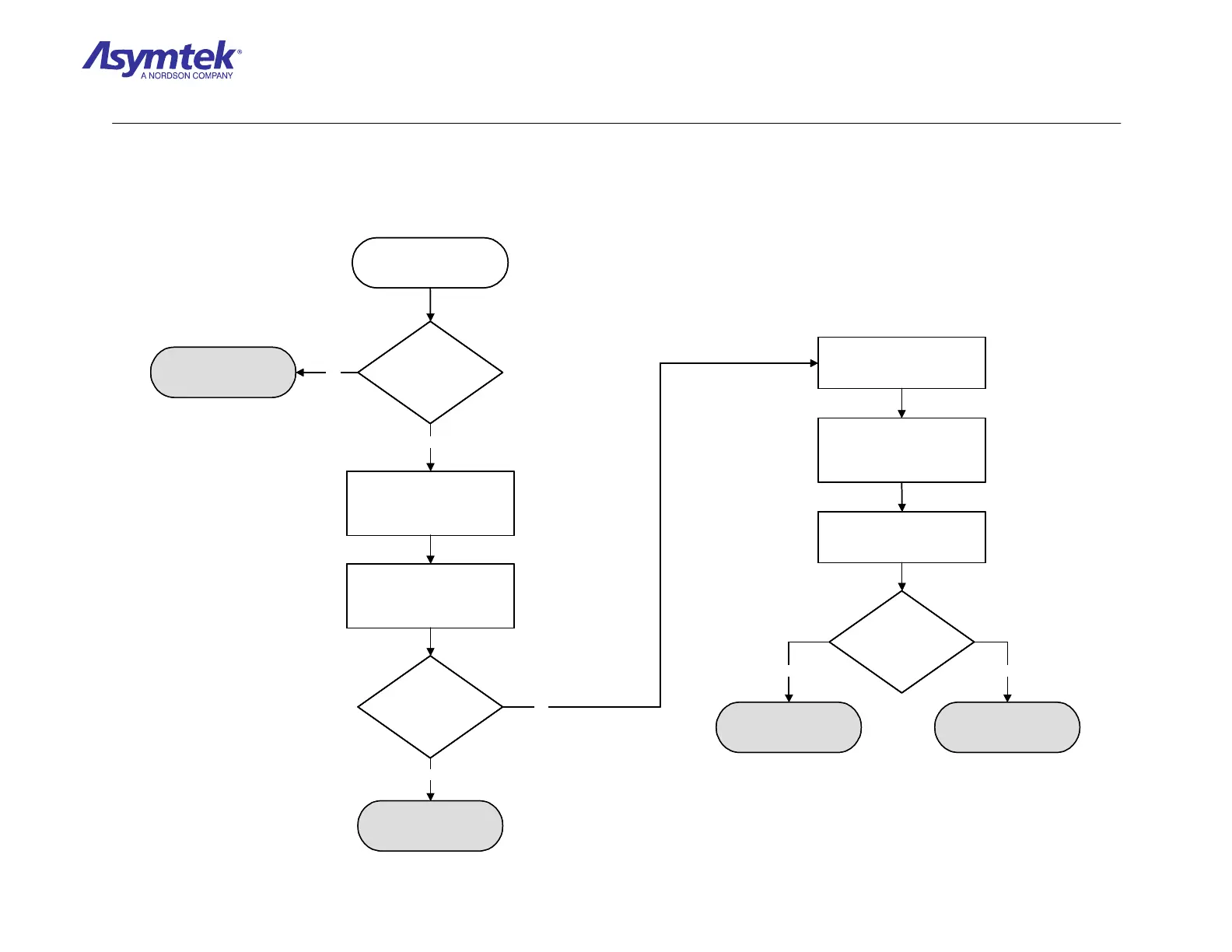
Is the green +SERVO
LED illuminated?
Press the black OFF (0)
button on the Operator’s
Console.
Go to Servo Power
Verification Procedure
Measure VDC between Pin 1
and Pin 2 of Power Cable
(P/N 06-4534-00) connected
to J26.
Locate the J26 power
connection at on the X and Y
Servo Amplifier PWAs on the
Servo Shelf.
Is the reading
67.5 ±2 VDC?
Disconnect the cable from the
Z-Servo Interface PWA
located at the rear of the
Dispensing Head.
Is the reading
67.5 ±2 VDC?
Z Servo Interface PWA
(P/N 60-1210-01) has
failed
Cable (P/N 60-1212-00)
has failed
Servo Amplifier (P/N 60-
1212-00) has failed
Locate the XY Servo
Interface PWA power LEDs.
Measure VDC between Pin 1
and Pin 2 of the cable
connector.
No
Yes
No
Yes
NoYes
Is the green +SERVO
LED illuminated?
Is the green +SERVO
LED illuminated?
Press the black OFF (0)
button on the Operator’s
Console.
Go to Servo Power
Verification Procedure
Measure VDC between Pin 1
and Pin 2 of Power Cable
(P/N 06-4534-00) connected
to J26.
Locate the J26 power
connection at on the X and Y
Servo Amplifier PWAs on the
Servo Shelf.
Is the reading
67.5 ±2 VDC?
Is the reading
67.5 ±2 VDC?
Disconnect the cable from the
Z-Servo Interface PWA
located at the rear of the
Dispensing Head.
Is the reading
67.5 ±2 VDC?
Is the reading
67.5 ±2 VDC?
Z Servo Interface PWA
(P/N 60-1210-01) has
failed
Cable (P/N 60-1212-00)
has failed
Servo Amplifier (P/N 60-
1212-00) has failed
Locate the XY Servo
Interface PWA power LEDs.
Measure VDC between Pin 1
and Pin 2 of the cable
connector.
No
Yes
No
Yes
NoYes
Diagram Sheet 4-5-10
Z Servo Amplifier Fault Isolation Procedure - Power-up Reset Check
 Loading...


