Training Guide Course No. 196514
Level 2 Maintenance, X-1000 Series Dispensing Systems 4-138 P/N 196515 (Revision A)
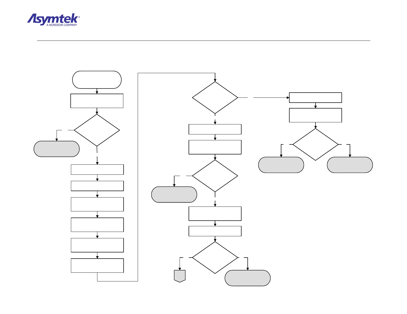
Ensure Cable is securely
connected
In the FmNT Main Window, click
on Tools.
In the Tools Window, click on I/O
Test and then click on the
Dispenser button.
In the I/O Test Dialog Window,
click on the PIO 96 Channels
10-13 tab.
Under the Channel 12 section of
the window, locate the
TACTILE_SENSE [4B5] signal.
Secure connection to the
Dispensing Calibration Module
and Main Interface PWA.
Inspect the Cable (P/N 06-
4599-00) for damage.
Is the cable damaged?
Cable (P/N 06-4599-00)
has failed.
No
Gently depress the Tactile
Sensor on the Dispensing
Calibration Module.
Does input for
TACTILE_SENSE/
[4B5] change from
high (1)
to low (0)?
Locate U15 on the Main
Interface PWA.
Measure VDC between Pin 14
and Pin 13 on U15 while toggling
the Tactile Sensor.
Does the signal
change from 5 VDC to
0 VDC?
Locate the backside of J24 on
the Main Interface PWA labeled
NEEDLE SENSOR.
Measure VDC between Pin 4
and Pin 5 on J24.
Is the reading 24
VDC?
Locate U22 on the Main
Interface PWA.
No
Measure VDC at Pin 3 on U22
while toggling the Tactile Sensor
(use TP1 for ground).
No
Yes
Does the signal
change from 5 VDC to
0 VDC?
Contact Asymtek
Technical Support
Main Interface PWA (P/N
60-1200-00) has failed
Yes No
Yes
Main Interface PWA (P/N
60-1200-00) has failed.
A
Main Interface PWA (P/N
60-1200-00) has failed.
Yes
Yes No
Ensure Cable is securely
connected
In the FmNT Main Window, click
on Tools.
In the Tools Window, click on I/O
Test and then click on the
Dispenser button.
In the I/O Test Dialog Window,
click on the PIO 96 Channels
10-13 tab.
Under the Channel 12 section of
the window, locate the
TACTILE_SENSE [4B5] signal.
Secure connection to the
Dispensing Calibration Module
and Main Interface PWA.
Inspect the Cable (P/N 06-
4599-00) for damage.
Is the cable damaged?Is the cable damaged?
Cable (P/N 06-4599-00)
has failed.
No
Gently depress the Tactile
Sensor on the Dispensing
Calibration Module.
Does input for
TACTILE_SENSE/
[4B5] change from
high (1)
to low (0)?
Does input for
TACTILE_SENSE/
[4B5] change from
high (1)
to low (0)?
Locate U15 on the Main
Interface PWA.
Measure VDC between Pin 14
and Pin 13 on U15 while toggling
the Tactile Sensor.
Does the signal
change from 5 VDC to
0 VDC?
Does the signal
change from 5 VDC to
0 VDC?
Locate the backside of J24 on
the Main Interface PWA labeled
NEEDLE SENSOR.
Measure VDC between Pin 4
and Pin 5 on J24.
Is the reading 24
VDC?
Is the reading 24
VDC?
Locate U22 on the Main
Interface PWA.
No
Measure VDC at Pin 3 on U22
while toggling the Tactile Sensor
(use TP1 for ground).
No
Yes
Does the signal
change from 5 VDC to
0 VDC?
Does the signal
change from 5 VDC to
0 VDC?
Contact Asymtek
Technical Support
Main Interface PWA (P/N
60-1200-00) has failed
Yes No
Yes
Main Interface PWA (P/N
60-1200-00) has failed.
A
Main Interface PWA (P/N
60-1200-00) has failed.
Yes
Yes No
Diagram Sheet 4-11-2
Needle Sensor/Tactile Sensor Fault Isolation Procedure – Tactile Sensor Verification
 Loading...


