893-00992-E
xiii
Figures
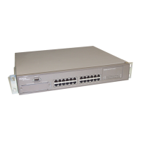
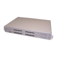
Figure 1-1. BayStack 350 Series Autosense Switch ..................................................1-1
Figure 1-2. Front-panel components ..........................................................................1-2
Figure 1-3. Back-panel components ..........................................................................1-4
Figure 1-4. BayStack 350 Switch Security Feature ....................................................1-8
Figure 1-5. Configuring power workgroups ..............................................................1-14
Figure 1-6. Configuring power workgroups and a shared media hub ......................1-15
Figure 1-7. Port-based VLAN example ....................................................................1-16
Figure 1-8. VLANs spanning multiple switches ........................................................1-17
Figure 1-9. Multiple VLANs sharing resources .........................................................1-18
Figure 1-10. VLAN configuration spanning multiple BayStack 350 switches .............1-19
Figure 1-11. VLAN Configuration screen for switch SW1 ...........................................1-20
Figure 1-12. VLAN Configuration screen for switch SW2 ...........................................1-21
Figure 1-13. VLAN Configuration screen for switch SW3 ...........................................1-22
Figure 1-14. VLAN Configuration screen for switch SW4 ...........................................1-23
Figure 1-15. Inter-switch trunk configuration example ................................................1-25
Figure 1-16. Server trunk configuration example .......................................................1-27
Figure 1-17. Client/server configuration example .......................................................1-28
Figure 1-18. Choosing the Server Trunk Configuration screen ..................................1-29
Figure 1-19. Server Trunk Configuration screen for Switch SW1 ...............................1-30
Figure 1-20. Choosing the Inter-Switch Trunk Configuration screen ..........................1-31
Figure 1-21. Inter-Switch Trunk Configuration screen example ..................................1-32
Figure 1-22. VLAN Configuration screen example for switch SW1 (1 of 2) ................1-34
Figure 1-23. VLAN Configuration screen example for switch SW1 (2 of 2) ................1-35
Figure 1-24. Trunk Configuration screen for switch SW2 ...........................................1-36
Figure 1-25. Trunk Configuration screen for switch SW3 ...........................................1-37
Figure 1-26. Trunk Configuration screen for switch SW4 ...........................................1-39
Figure 1-27. Path cost arbitration example .................................................................1-42
Figure 1-28. Example 1: Correctly configured trunk .................................................1-43
Figure 1-29. Example 2: Detecting a misconfigured port ...........................................1-44
 Loading...