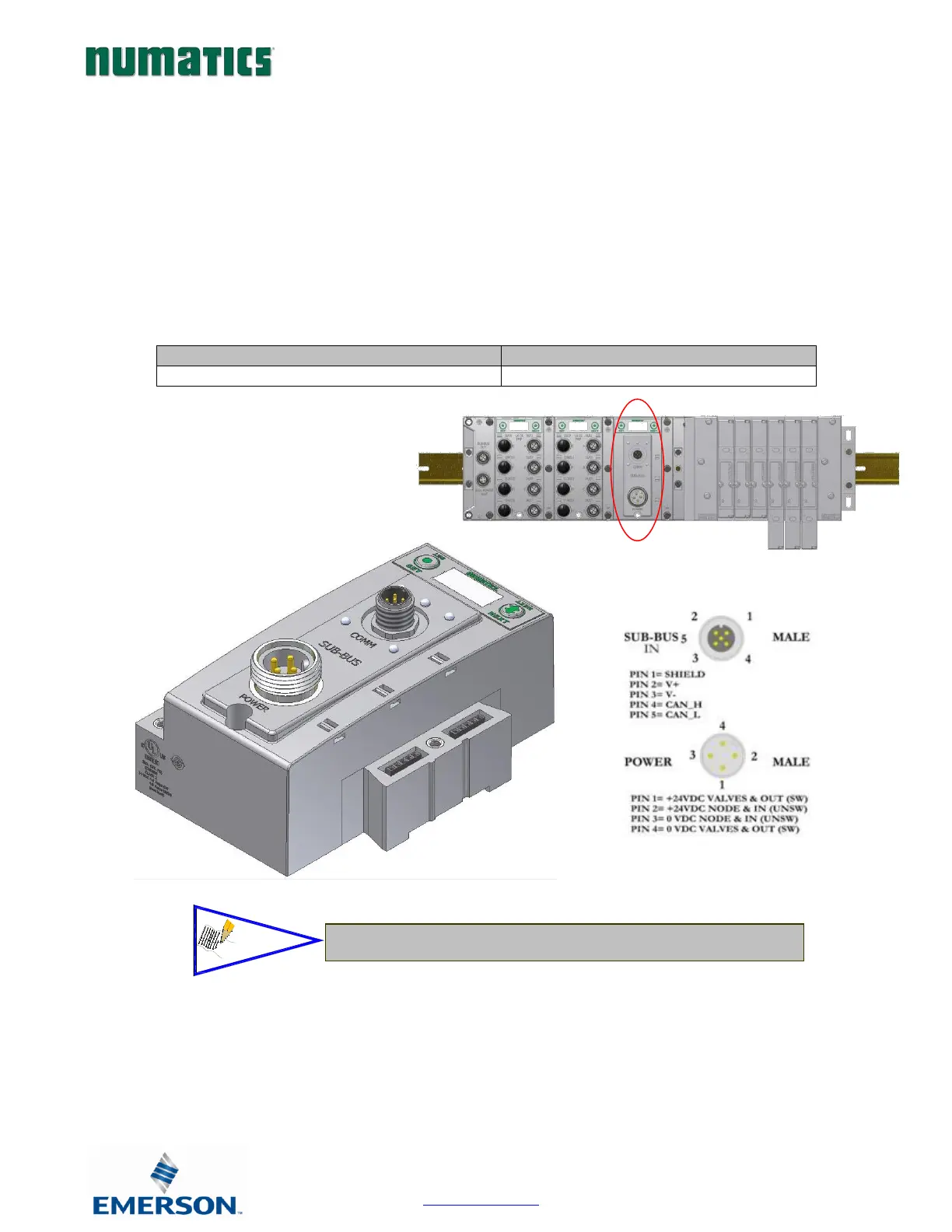
Sub-Bus Valve Module
• COMM - 5 pin M12 male Sub-Bus input communication connector.
• Must be connected to the SUB-BUS OUT connector of the previous assembly
• Carries 24 VDC power for electronics of module
• POWER - 4 pin MINI male power connector.
• Power is required for Outputs
• Used to distribute Valves on the Sub-Bus.
• Can accept discrete I/O modules to allow a Sub-Bus Valve manifold with I/O