683311W
4-46
Proceed as follows using an oscilloscope equipped with memory:
- Connect the oscilloscope ground to pin 2 (GND) and the probe signals to pin 1 (OUT1) of connector
J6 on the PR2VER board.
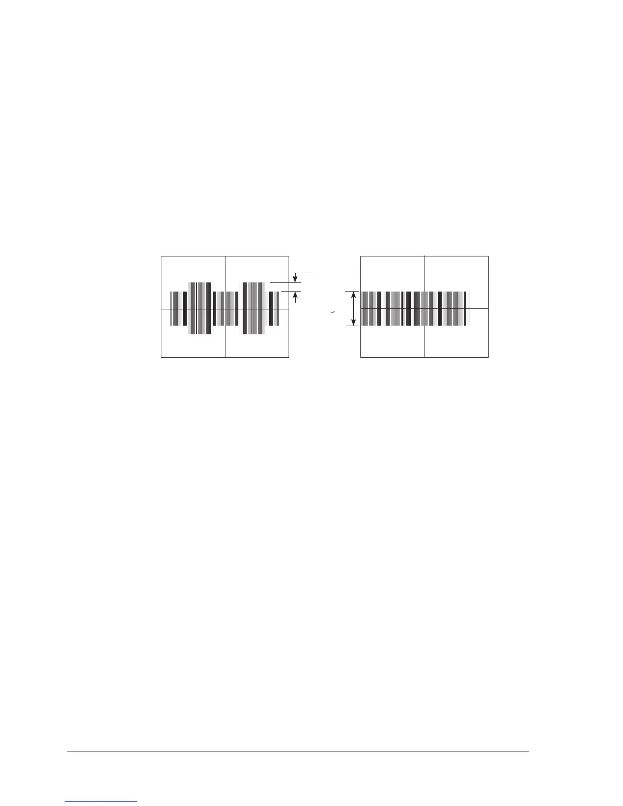
- Insert the "Amplitude and Skew Sample" chart code 751883Y from the Skew Control side. Record
the signal read during ejection movement.
The signal recorded must not have a spread greater than 0.4 V. No action needs to be undertaken.
- Insert the "Amplitude and Skew Sample" chart code 751883Y from the Jitter/Ampl side.
Record the signal read during ejection movement. If the signal recorded does not reach 4 V peak-
to-peak, the assembly needs to be replaced.
Fig. 4-7
> 4 V
SKEW JITTER
0,4 V