103
Fail-safe Circuits Section 4-1
as a RUN output. Connect an external relay (CR1) to this RUN output as
shown in the following diagram.
Note Use the Always ON Flag (SR 25213) as an execution condition for an Output
from the Output Unit.
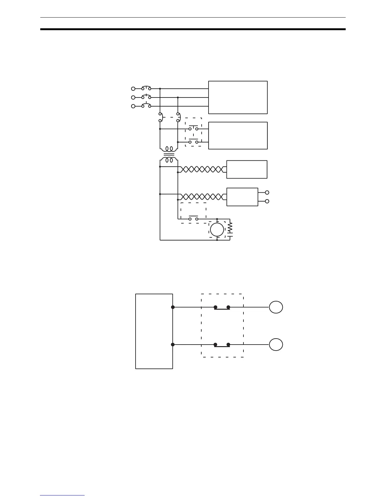
Interlock Circuits When the PC controls an operation such as the clockwise and counterclock-
wise operation of a motor, provide an external interlock such as the one
shown below to prevent both the forward and reverse outputs from turning ON
at the same time.
This circuit prevents outputs MC1 and MC2 from both being ON at the same
time even if IR 10001 and IR 10002 are both ON, so the motor is protected
even if the PC is programmed improperly or malfunctions.
MCB1
MCB2
CR1
Power supply
Controlled system
DC voltage
regulator
Transformer
or noise filter
Twisted pair
ON during
operation
+
–
DC
input/output
CR1 Surge suppressor
CQM1H PC
PC
MC2
MC1
10001
10002
MC1
MC2
Motor clockwise
Motor counterclockwise
Interlock circuit

 Loading...


