235
Appendix
Preparing Cables for Inner Boards
This appendix describes methods for creating CN1 and CN2 cables for the following Inner Boards. The meth-
ods are the same for all the Boards.
• CQM1H-CTB41 High-speed Counter Board
• CQM1H-PLB21 Pulse I/O Board
• CQM1H-ABB21 Absolute Encoder Interface Board
• CQM1H-MAB42 Analog I/O Board
Applicable Connector (on the Cable)
Use the following products or equivalents for the connector on the cable.
Socket: XM2D-1501 (OMRON)
Hood: XM2S-1511 (OMRON)
Two of each of the above products are provided as standard accessories for the CQM1H-CTB41/PLB21/
ABB21/MAB42 Inner Boards.
Cable
Use shielded twisted-pair wire for the cable.
Wiring and Assembly
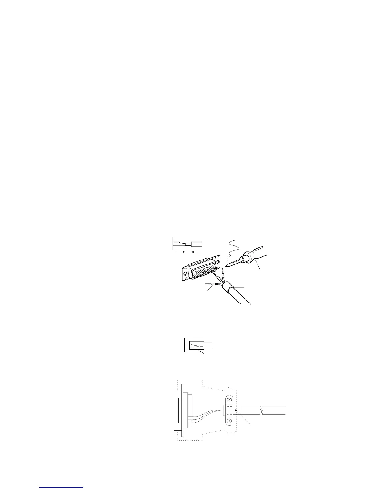
The following illustrations show the procedure for wiring and assembly of the connectors. First pass the signal
wires through heat-shrinking tubes and solder them to the socket pins.
Note Always check the wiring before supplying power.
After soldering all of the necessary pins, slide the heat-shrinking tubes over the soldered areas of the respec-
tive wires. Then shrink the tubes by heating them with a jet of hot air.
Assemble the socket and hood as shown in the illustration below. At the connector on the CQM1H side, wrap
aluminum tape around the twisted wire as shown in the illustration, and secure the wire to the hood.
1 mm
Soldering iron
Fold back the shield.
Heat-shrinking tube
Inner diameter: 1.5 mm, l = 10
Heat-shrinking tube
End connected to FG
Aluminum foil tape

 Loading...


