215
Absolute Encoder Interface Board Section 8-3
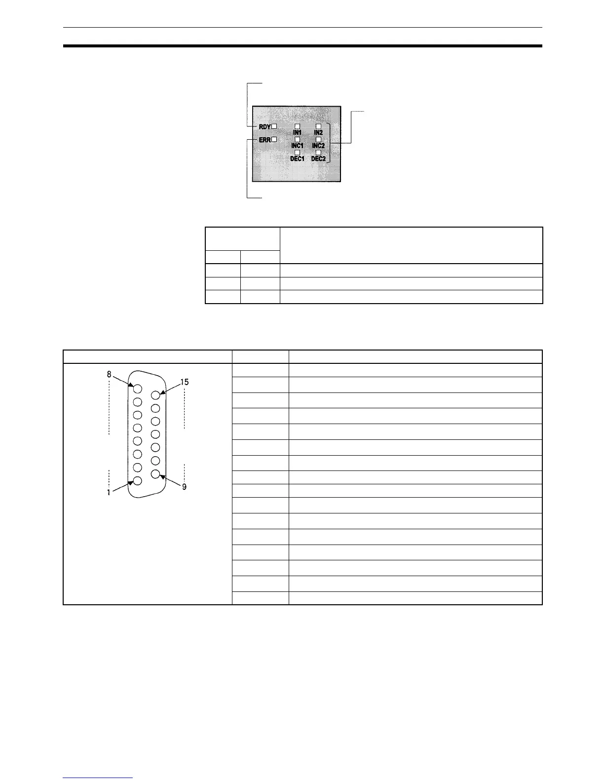
LED Indicators
8-3-6 Pin Arrangement of Connectors CN1 and CN2
CN1 and CN2 have identical pin arrangements.
Note 1. Refer to Appendix A Preparing Cables for Inner Boards for information
about using a compatible connector (XM2D-1501 Socket with XM2S-1511
Hood) to construct a cable. When connecting to an absolute encoder man-
ufactured by OMRON, the E69-DC5 Absolute Encoder Interface Board
Connecting Cable (described below) can be used.
2. Only absolute encoders that produce binary gray code outputs can be
used.
Encoder input
indicators
Function
Port 1 Port 2
IN1 IN2 Lit when input bit 0 is ON.
INC1 INC2 Lit when value input is incremented.
DEC1 DEC2 Lit when value input is decremented.
Ready (green)
Lit when the Absolute Encoder Interface Board is ready.
Error (red)
Lit when there is an error in the PC Setup for the Absolute
Encoder Interface Board.
Encoder input (orange)
Refer to the following table.
Pin arrangement Pin No. Name
1 Common input
2
Bit 2
11
of binary gray code from encoder
3
Bit 2
9
of binary gray code from encoder
4
Bit 2
7
of binary gray code from encoder
5
Bit 2
5
of binary gray code from encoder
6
Bit 2
3
of binary gray code from encoder
7
Bit 2
1
of binary gray code from encoder
8 Not used.
9 Common input
10
Bit 2
10
of binary gray code from encoder
11
Bit 2
8
of binary gray code from encoder
12
Bit 2
6
of binary gray code from encoder
13
Bit 2
4
of binary gray code from encoder
14
Bit 2
2
of binary gray code from encoder
15
Bit 2
0
of binary gray code from encoder
Hood Not used.

 Loading...


