193
High-speed Counter Board Section 8-1
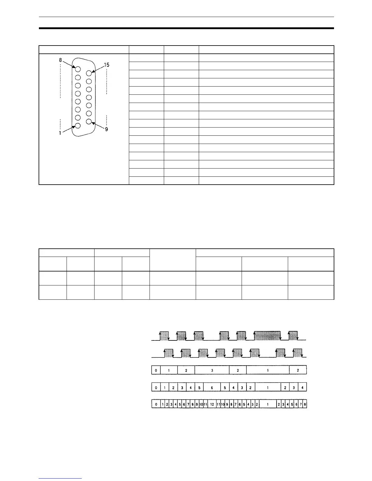
CN2: Pulse Input 3 and 4
Note Refer to Appendix A Preparing Cables for Inner Boards for information about
using a compatible connector (XM2D-1501 Socket with XM2S-1511 Hood) to
construct a cable.
8-1-7 Wiring Examples
Pulse Input Connections Connect the encoder outputs to CN1 and CN2 as shown below according to
the port’s Input Mode.
Note Pin numbers for negative pins are given in parentheses.
Pin arrangement Pin No. Name Function
1 3Z– Counter 3 input: Z –
2 3Z+ Counter 3 input: Z +
3 3B– Counter 3 input: B –
4 3B+ Counter 3 input: B +
5 3A– Counter 3 input: A –
6 3A+ Counter 3 input: A –
7 4OUT External output 4
8 3OUT External output 3
9 4Z– Counter 4 input: Z –
10 4Z+ Counter 4 input: Z +
11 4B– Counter 4 input: B –
12 4B+ Counter 4 input: B +
13 4A– Counter 4 input: A –
14 4A+ Counter 4 input: A +
15 –DC Power supply for external outputs 1 to 4: 0 V
Hood NC Not used.
CN1 pins CN2 pins Signal name Encoder output
Port 1 Port 2 Port 3 Port 4 Differential
Phase Mode
Pulse/Direction
Mode
Up/Down Mode
8 (7) 15 (14) 6 (5) 14 (13) Encoder input A Encoder phase A
input
Pulse input Increment pulse
input
6 (5) 13 (12) 4 (3) 12 (11) Encoder input B Encoder phase B
input
Directional sig-
nal input
Decrement pulse
input
Phase A
Differential Phase Mode
Phase B
1x
2x
4x

 Loading...


