226
Analog I/O Board Section 8-5
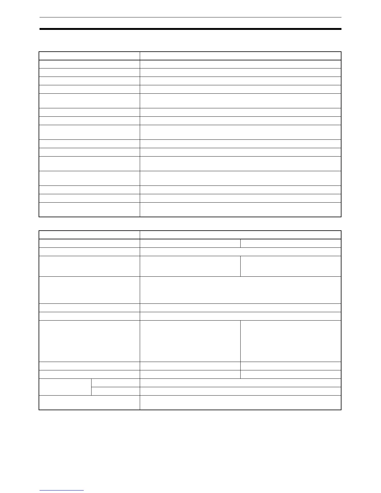
8-5-8 Specifications
Analog Inputs
Note 1. Separate input signal ranges can be set for each input.
2. The A/D conversion time is the time taken for an analog signal to be stored
in memory as digital data. At least one cycle is required to transfer the data
to the CPU Unit.
3. The overall precision is the precision with respect to full scale.
Item Specifications
Name Analog I/O Board
Model number CQM1H-MAB42
Applicable CPU Unit CQM1H-CPU51/61
Unit classification CQM1H-series Inner Board
Mounting locations and number of
Boards
1 Board in Inner Board slot 2 (right slot)
Analog inputs 4 inputs (Refer to Analog Inputs below for a details.)
Analog outputs 2 outputs (Refer to Analog Outputs below for a details.)
Isolation method Between inputs and PC: Photocoupler isolation
Between inputs: No isolation
Settings None
Indicators 2 LED indicators on front panel: Ready (RDY) and Error (ERR)
Front connection section Connectors CN1 and CN2 (Compatible connector: Sockets & connectors pro-
vided as standard accessories.)
Current consumption (Supplied from
Power Supply Unit)
5 V DC 400 mA max.
Dimensions 25 × 110 × 107 mm (W × H × D)
Weight 100 g max.
Standard accessories Sockets:XM2D-1501 (OMRON) x 2
Hoods:XM2S-1511 (OMRON) x 2
Item Specifications
Input signals Voltage inputs Current inputs
Number of analog input points 4 inputs
Input signal ranges (See note 1) –10 to 10 V
0 to 10 V
0 to 5 V
0 to 20 mA
Analog input storage words Analog input 1: IR 232
Analog input 2: IR 233
Analog input 3: IR 234
Analog input 4: IR 235
A/D conversion time (See note 2) 1.7 ms max./point
Resolution 1/4,096
A/D conversion output data 12-bit binary data
–10 to +10 V: F800 to 07FF Hex
0 to 10 V, 0 to 5 V: 0000 to 0FFF Hex
Note Negative voltages (–10 V ≤
input voltage < 0 V) are stored
as two’s complements.
12-bit binary data
0 to 20 mA: 0000 to 0FFF Hex
External input impedance 1 MΩ typical 250 Ω typical
Absolute maximum rated input ±15 V ±30 mA
Overall precision
(See note 3)
23±2°C ±0.5% of FS
0 to 55°C ±1.0% of FS
Control Bits PC Setup settings are used to determine whether or not to convert analog sig-
nals into binary data for each input.

 Loading...


