41
Overview Application Procedure Section 1-6
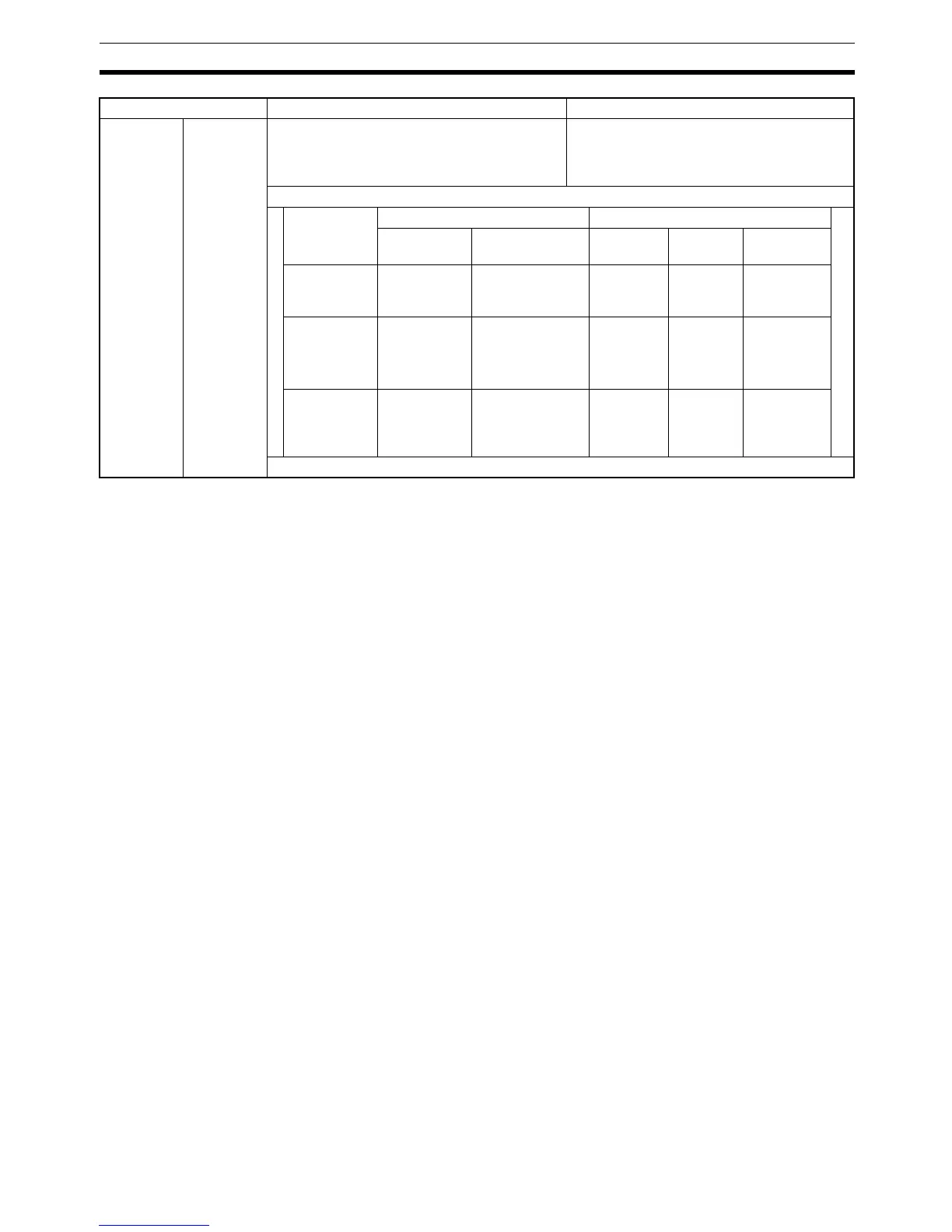
Note There is a difference in timing, but there is no difference in functionality.
1-6 Overview Application Procedure
The following procedure outlines the steps necessary to set up, program, and
operate a CQM1H control system.
1,2,3... 1. Determine the system configuration.
Decide if one or more Inner Boards are required in the system and whether
they are to be mounted in the left or right slot. The following boards are
available.
• Serial Communications Board for serial communications.
• High-speed Counter Board or Pulse I/O Board for high-speed counter
inputs.
• Pulse I/O Board or pulse outputs.
• Absolute Encoder Interface Board for inputs from an absolute encoder.
• Analog Setting Board to input settings via variable resistors.
• Analog I/O Board for analog I/O.
Also, decide if it will be necessary to connect to a Controller Link System.
2. Allocate I/O.
Nothing is required to allocate I/O with the CQM1H. I/O tables are not re-
quired and all I/O is allocated automatically. Words are allocated to I/O
Units starting at the CPU Unit and going to the right, with Input Units being
allocated words starting at IR 001 and Output Units being allocated words
starting at IR 100.
3. Set settings in the PC Setup.
The PC Setup can be used to control the functions of the CPU Unit and
Inner Boards. The default settings in the PC Setup must be confirmed and
if any changes are required, they must be made from a Programming De-
vice before starting operation. The PC Setup must be changed to use Inner
Boards.
Timing of
data area
changes
(See note.)
RS-232C
Reception
Completed
Flag
(AR 0806)
RS-232C
Reception
Overflow
Flag
(AR 0807)
Peripheral
Port Recep-
tion Com-
pleted Flag
(AR 0814)
Peripheral
Port Recep-
tion Over-
flow Flag
(AR 0815)
The Reception Completed Flags and Recep-
tion Overflow Flags are turned OFF after exe-
cution of RXD instruction is completed (during
program execution).
The Reception Completed Flags and Recep-
tion Overflow Flags are turned OFF in the
overseeing processes in the next cycle after
the RXD instruction is executed.
Example showing when the Reception Completed Flags are turned OFF:
CQM1H CQM1
Previous
cycle
Current cycle Previous
cycle
Current
cycle
Next cycle
Overseeing --- --- --- --- Reception
Completed
Flag OFF
Program exe-
cution
--- RXD instruction
execution
Reception Com-
pleted Flag OFF
--- RXD
instruc-
tion exe-
cution
---
Peripheral
servicing
Reception
Completed
Flag ON
--- Reception
Com-
pleted Flag
ON
--- ---
Item CQM1H CQM1

 Loading...


