224
Analog I/O Board Section 8-5
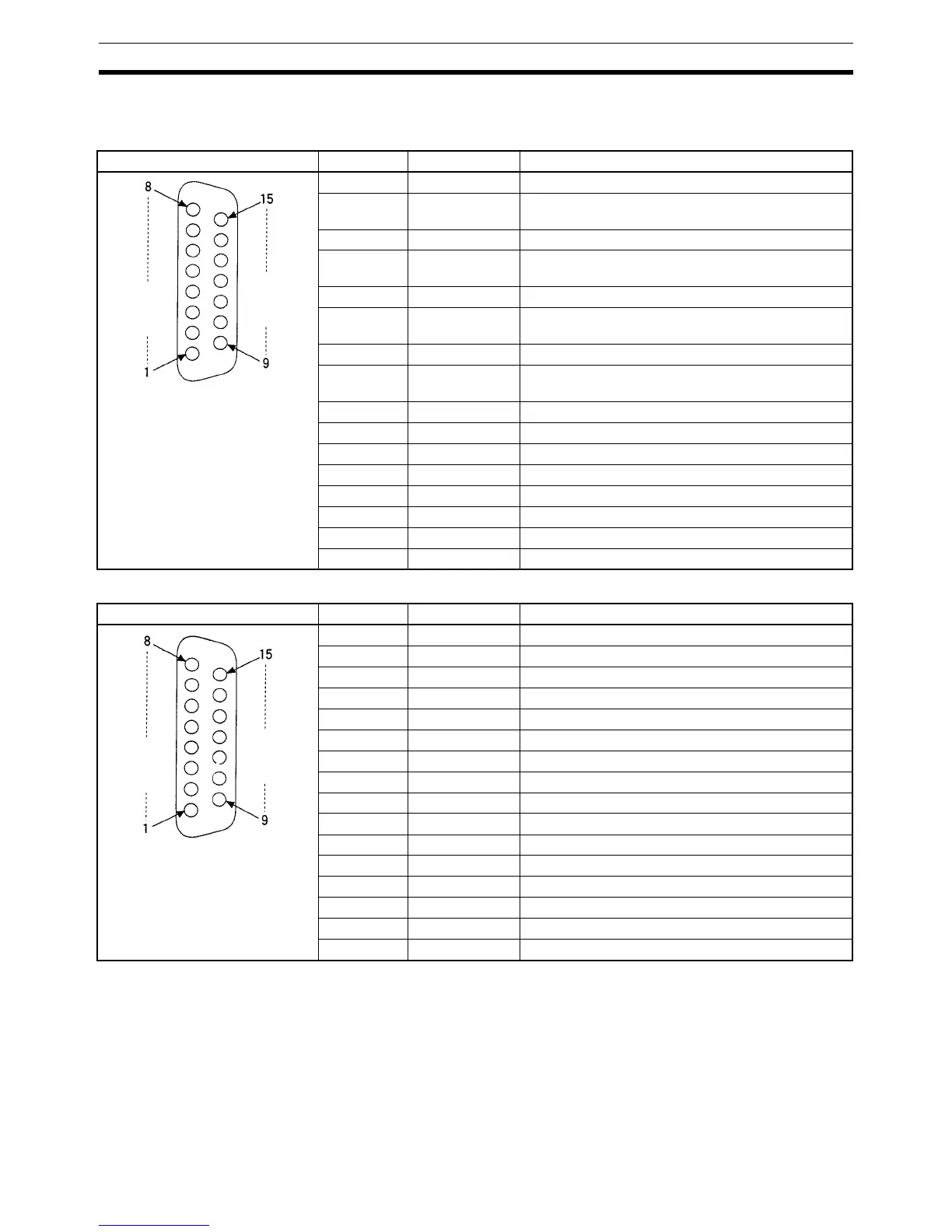
8-5-6 Pin Arrangement of Connectors CN1 and CN2
CN1: Analog Input
CN2: Analog Output
Note Refer to Appendix A Preparing Cables for Inner Boards for information about
using a compatible connector (XM2D-1501 Socket with XM2S-1511 Hood) to
construct a cable.
Pin arrangement Pin No. Name Function
1 V4+ Analog input 4: + voltage input
2 V4– Analog input 4: common (– voltage input, – current
input)
3 V3+ Analog input 3: + voltage input
4 V3– Analog input 3: common (– voltage input, – current
input)
5 V2+ Analog input 2: + voltage input
6 V2– Analog input 2: common (– voltage input, – current
input)
7 V1+ Analog input 1: + voltage input
8 V1– Analog input 1: common (– voltage input, – current
input)
9 I4+ Analog input 4: + current input
10 NC Not used.
11 I3+ Analog input 3: + current input
12 NC Not used.
13 I2+ Analog input 2: + current input
14 NC Not used.
15 I1+ Analog input 1: + current input
Hood NC Not used.
Pin arrangement Pin No. Name Function
1 NC Not used.
2 NC Not used.
3 I2– Analog output 2: common (– current output)
4 V2– Analog output 2: common (– voltage output)
5 NC Not used.
6 NC Not used.
7 I1– Analog output 1: common (– current output)
8 V1– Analog output 1: common (– voltage output)
9 NC Not used.
10 I2+ Analog output 2: + current output
11 V2+ Analog output 2: + voltage output
12 NC Not used.
13 NC Not used.
14 I1+ Analog output 1: + current output
15 V1+ Analog output 1: + voltage output
Hood NC Not used.

 Loading...


