202
Pulse I/O Board Section 8-2
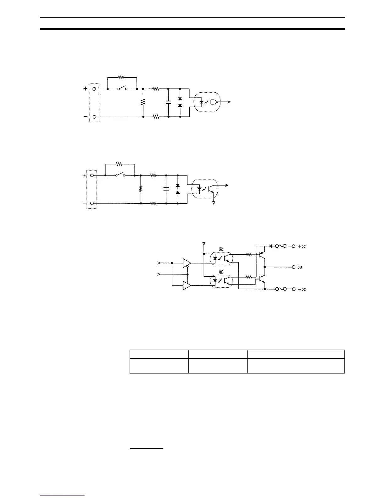
8-1-9 Internal Circuits
Pulse Inputs
External Outputs
Note In the above figure, A is active when sourcing outputs are set, and B is active
when sinking outputs are set.
8-2 Pulse I/O Board
8-2-1 Model
8-2-2 Function
The Pulse I/O Board is an Inner Board that supports two pulse inputs and two
pulse outputs.
Pulse Inputs 1 and 2 Pulse inputs 1 and 2 can be used as high-speed counters to count pulses
input at either 50 kHz (signal phase) or 25 kHz (differential phase). Interrupt
processing can be performed based on the present values (PV) of the
counters.
Input Mode
The following three Input Modes are available:
Phases A and B
Input voltage
switch.
See Note.
Internal circuit of phase A or B
Internal circuit of Z
Input voltage
switch.
See Note.
Phase Z
Note ON: Line driver input
OFF: 24-V DC input
4.4 kΩ
3.0 kΩ
Name Model Specifications
Pulse I/O Board CQM1H-PLB21 Two pulse input points and two pulse
output points
Internal circuit of Output
Sourcing/Sinking switching signal
0.75 A
0.75 A

 Loading...


