27
Functions Listed by Purpose Section 1-4
formed, enabling separate control and data transfer when required. In particu-
lar, direct setting using data links allows the creation of a flexible data link
system with effective use of data areas.
1-4 Functions Listed by Purpose
Purpose Unit/Board Function Details
System design Connecting 12 or more
I/O or Dedicated I/O
Units
I/O Control Unit
and I/O Interface
Unit
Using an
Expansion I/O
Block
You can connect up to 5 Units to
the CPU Block and 11 Units to the
Expansion I/O Block.
Installing a PC in a
narrow space
Cycle time settings Creating a minimum
cycle time
CPU Unit PC Setup: Cycle
Time, Minimum
Cycle Time
Set in DM 6619
(0001 to 9999 ms).
Stopping operation if
the cycle time exceeds
a set time
PC Setup: Cycle
Monitor Time
Set in DM 6618 (00 to 99; setting
units: 10 ms, 100 ms, 1 s).
Detecting when the
cycle time exceeds
100 ms
SR area: Cycle
Time Over Flag
SR 25309 turns ON.
Detecting the maximum
and current values of
the cycle time
AR area:
Maximum Cycle
Time, Current
Cycle Time
Maximum Cycle Time is stored in
AR 26, and the Current Cycle
Time is stored in AR 27.
Refresh method Refreshing an output
whenever an OUTPUT
instruction is executed
CPU Unit PC Setup:
Output Refresh
Method, Direct
Set direct output refresh method
in DM 6639 bits 00 to 07.
Output is refreshed when OUT is
executed in the user program.
Refreshing inputs when
an interrupt occurs
PC Setup: First
Input Refresh
Word and Number
of Input Refresh
Words for
interrupts
Set input refresh word for each
interrupt in DM 6630 to DM 6638.
The inputs for the specified words
will be refreshed before the
interrupt subroutine is executed
when input interrupt, interval timer
interrupt, or high-speed counter
interrupt occurs.
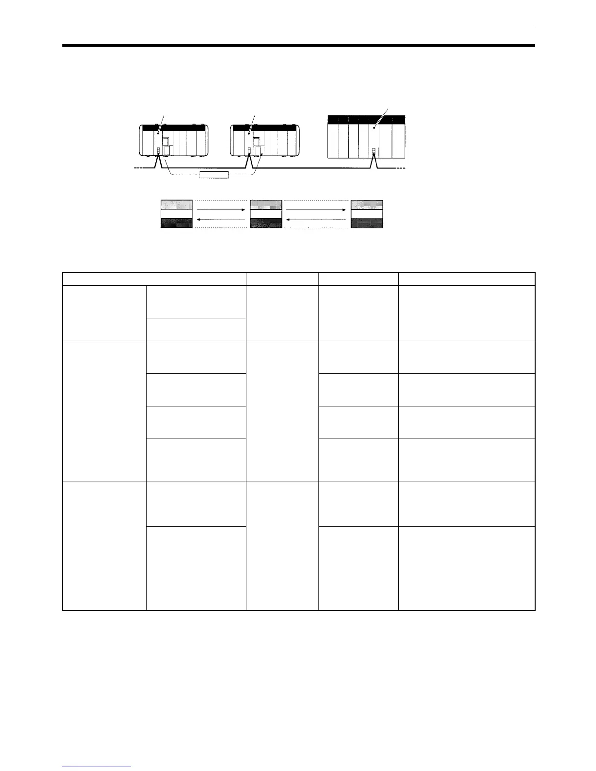
Controller Link Unit Controller Link Unit
Controller Link (wired)
CQM1H CQM1H
Controller Link Unit
CS-series, C200HX/HG/HE,
CVM1, or CV-series PC
Messages sent to other nodes
whenever necessary.
Data links automati-
cally transfer data
every cycle.

 Loading...


