227
Serial Communications Board Section 8-6
Analog Outputs
Note 1. Different terminals are used for each output, allowing output signal ranges
to be selected for each output.
2. The D/A conversion time is the time taken to convert the data in the CPU
Unit and output it. At least one cycle is required to transfer the data from
the CPU Unit to the Analog I/O Board.
3. The overall precision is the precision with respect to full scale.
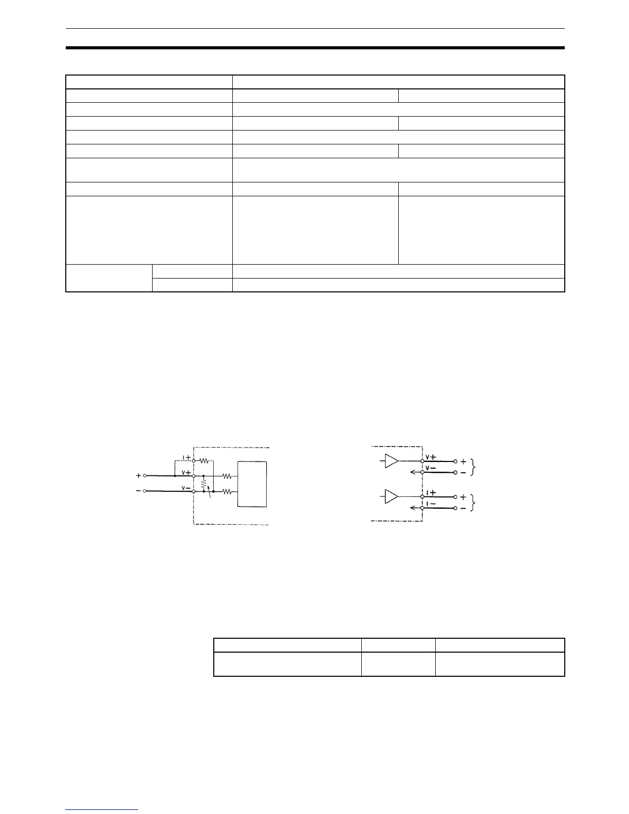
8-5-9 Internal Circuit Configuration
8-6 Serial Communications Board
This section provides an introduction to the Serial Communications Board.
Detailed information can be found in the Serial Communications Board Oper-
ation Manual (W365).
8-6-1 Model Number
8-6-2 Serial Communications Boards
The Serial Communications Board is an Inner Board for the CQM1H-series
PCs. One Board can be installed in Inner Board slot 1 of a CQM1H-series
CPU Unit. The Board cannot be installed in slot 2.
Item Specifications
Output signals Voltage outputs Current outputs
Number of analog output points 2 outputs
Output signal ranges (See note 1) –10 to 10 V 0 to 20 mA
D/A conversion time (See note 2) 1.7 ms max./2 points
Resolution 1/4,095 1/2,047
Analog output setting storage words Analog output 1: IR 236
Analog output 2: IR 237
External output impedance 2 kΩ min. 350 Ω max.
Setting data 12-bit binary data
–10 to +10 V: F800 to 07FF Hex
Note Negative voltages outputs (–10
V ≤ output voltage < 0 V) need
to be stored as two’s
complements.
11-bit binary data
0 to 20 mA: 0000 to 07FF Hex
Overall precision
(See note 2)
23±2°C ±0.5% of FS
0 to 55°C ±1.0% of FS
Analog Inputs Analog Outputs
Analog I/O Board
(Common for each output)
(Common for each output)
Voltage output
Current output
0 V
0 V
Analog I/O Board
(Connect only when
using current input.)
Multi-
plexer
250 Ω
10 kΩ
1 MΩ
10 kΩ
Name Model Specifications
Serial Communications Board CQM1H-SCB41 One RS-232 port
One RS-422A/485 port

 Loading...


