11
System Configuration Section 1-2
Mounting Combinations
Note 1. High-speed Counter Boards can be mounted in both slots of the CQM1H-
CPU51/61 simultaneously.
2. Analog Setting Boards cannot be mounted in both slots of the CQM1H-
CPU51/61 simultaneously.
1-2-5 Communications Units
Note A Communications Unit is connected between the Power Supply Unit and the
CPU Unit. Communications Units cannot be connected to Expansion I/O
Blocks.
Analog I/O Board Analog inputs of 0 to 5 V, 0 to 20 mA, –10 to +10 V: 4 points
Analog outputs of 0 to 20 mA, –10 to +10 V: 2 points
CQM1H-MAB42
Serial Communications Board One RS-232C port and one RS-422A/485 port CQM1H-SCB41
Name Specifications Model number
CPU Unit and slot Inner Board
High-speed
Counter
Board
Pulse I/O
Board
Absolute
Encoder
Interface
Board
Analog Set-
ting Board
Analog I/O
Board
Serial Com-
munications
Board
CQM1H-
CTB41
CQM1H-
PLB21
CQM1H-
ABB21
CQM1H-
AVB41
CQM1H-
MAB42
CQM1H-
SCB41
CQM1H-
CPU61/51
Slot 1
(left slot)
OK Not possible Not possible OK Not possible OK
Slot 2
(right slot)
OK OK OK OK OK Not possible
CQM1H-CPU21/11 Not possible Not possible Not possible Not possible Not possible Not possible
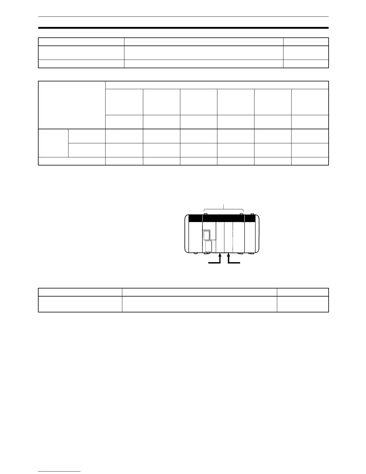
CQM1H CPU Unit
Slot 1 for Inner Boards (left slot) Slot 2 for Inner Boards (right slot)
Name Specifications Model
Controller Link Unit (wired) Data link (Maximum number of words per node: 8,000)
Message communications (SEND/RECV/CMND instructions)
CQM1H-CLK21

 Loading...


