106
Mounting Dimensions Section 4-3
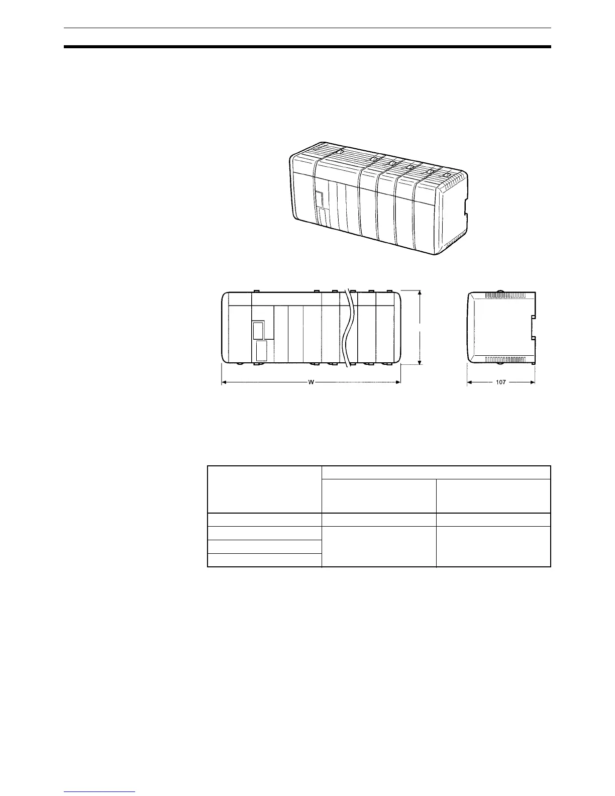
4-3 Mounting Dimensions
The following diagram shows a CQM1H PC consisting of a Power Supply
Unit, Communications Unit, CPU Unit, and I/O Units. Be sure to connect an
End Cover to the right side of the Unit on the opposite end of the PC from the
CPU Unit.
External Dimensions for
CPU Block
The following table lists the total width, W, of the PC.
n = No. of I/O Units + No. of Dedicated I/O Units.
Note For example, if a CQM1-CPU51/61 Power Supply Unit is used and there is a
total of four I/O Units and Dedicated I/O Units, the width would be 347 mm.
W = 32
× 4 + 219 = 347 mm
If a Communications Unit is connected to the CQM1-CPU51/61, add 32 mm
to obtain the total width.
Power Supply Unit Width (mm)
CPU Block only
0 ≤ n ≤ 11
With Expansion I/O Block
connected
0 ≤ n ≤ 5
CQM1-PA203 32 × n + 187 32 × n + 219
CQM1-PA206 32 × n + 219 32 × n + 251
CQM1-PA216
CQM1-PD026
Unit: mm
117.5

 Loading...


