225
Analog I/O Board Section 8-5
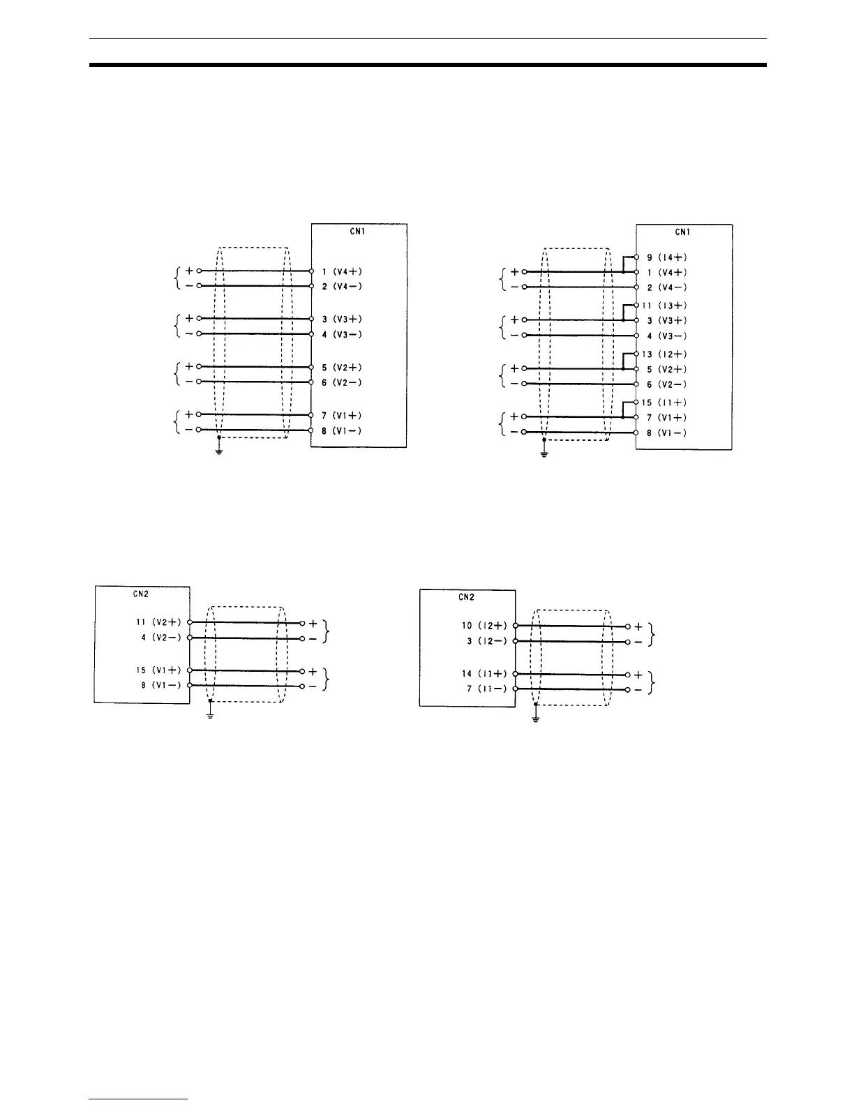
8-5-7 Wiring Examples
Analog Input
Connections
The input signal connections to CN1 depend on whether the input signals are
voltage inputs or current inputs. The following diagrams show the correct wir-
ing in each case.
Analog Output
Connections
The output signal connections to CN2 depend on whether the output signals
are voltage outputs or current outputs. The following diagrams show the cor-
rect wiring in each case.
Voltage Inputs
(–10 to +10 V, 0 to 10 V, or 0 to 5 V)
Current Inputs
(0 to 20 mA)
Analog I/O Board Analog I/O Board
Pin No.
Pin No.
Analog input 4
Shield Shield
Analog input 3
Analog input 2
Analog input 1
Analog input 4
Analog input 3
Analog input 2
Analog input 1
Voltage Outputs
(–10 to +10 V)
Current Outputs
(0 to 20 mA)
Analog I/O Board Analog I/O Board
Pin No.Pin No.
Analog output 2
Shield Shield
Analog output 1
Analog output 2
Analog output 1

 Loading...


