192
High-speed Counter Board Section 8-1
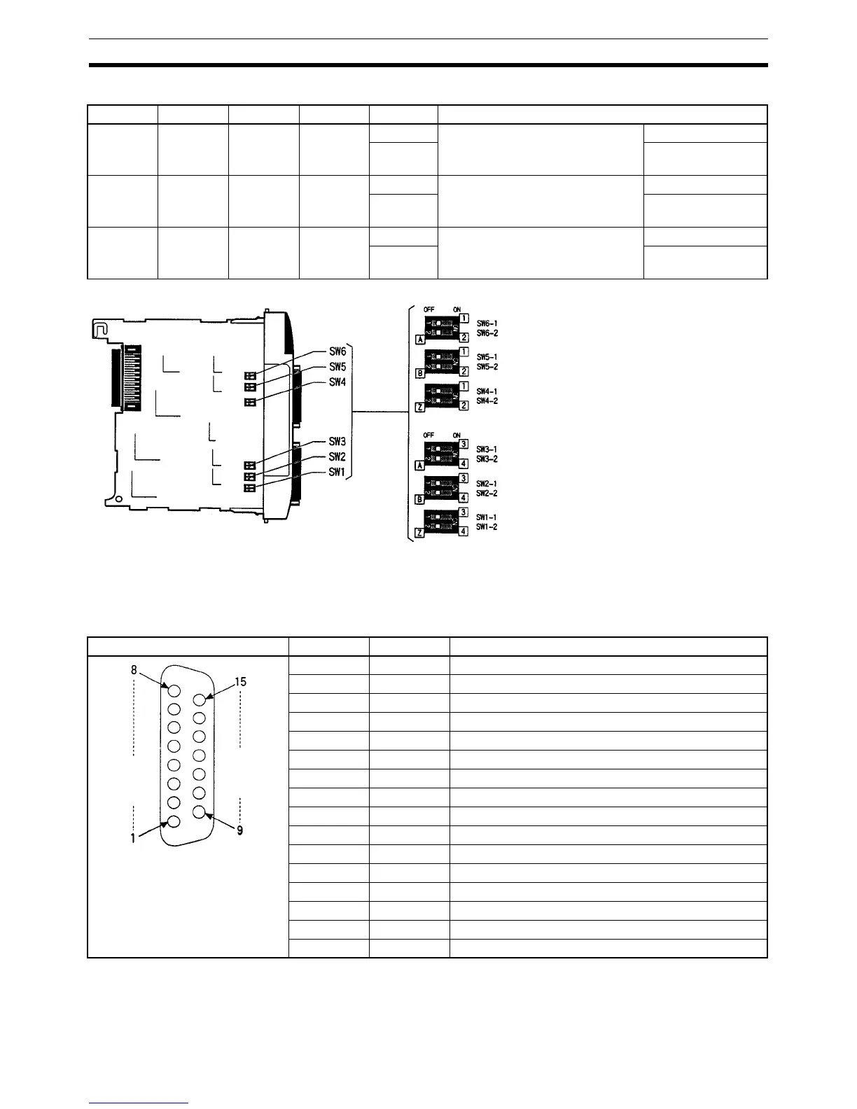
Input Voltage Level Switches
8-1-6 Pin Arrangement of Connectors CN1 and CN2
CN1: Pulse Input 1 and 2
Counter 1 Counter 2 Counter 3 Counter 4 Status Setting
SW6-1 SW6-2 SW3-1 SW3-2 ON Counter input: Input voltage A Line driver level
OFF 24-V DC level
(default)
SW5-1 SW5-2 SW2-1 SW2-2 ON Counter input: Input voltage B Line driver level
OFF 24-V DC level
(default)
SW4-1 SW4-2 SW1-1 SW1-2 ON Counter input: Input voltage Z Line driver level
OFF 24-V DC level
(default)
Phase A, High-speed counter 1
High-speed counter 2
Left side of Board
Phase B, High-speed counter 1
High-speed counter 2
Phase Z, High-speed counter 1
High-speed counter 2
Phase A, High-speed counter 3
High-speed counter 4
Phase B, High-speed counter 3
High-speed counter 4
Phase Z, High-speed counter 3
High-speed counter 4
Pin arrangement Pin No. Name Function
1 2OUT External output 2
2 1OUT External output 1
3 1Z– Counter 1 input: Z –
4 1Z+ Counter 1 input: Z +
5 1B– Counter 1 input: B –
6 1B+ Counter 1 input: B +
7 1A– Counter 1 input: A –
8 1A+ Counter 1 input: A +
9 +DC Power supply for external outputs 1 to 4: 5 to 24 V DC
10 2Z– Counter 2 input: Z –
11 2Z+ Counter 2 input: Z +
12 2B– Counter 2 input: B –
13 2B+ Counter 2 input: B +
14 2A– Counter 2 input: A –
15 2A+ Counter 2 input: A +
Hood NC Not used.

 Loading...


