205
Pulse I/O Board Section 8-2
LED Indicators
Pulse Output Indicators
Pulse Input Indicators
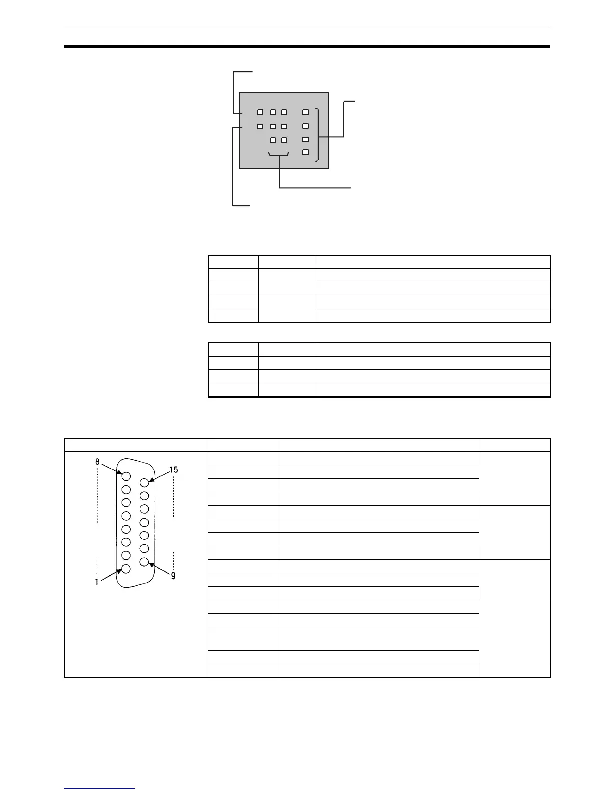
8-2-6 CN1 and CN2 Pin Arrangement
The pin arrangements of connectors CN1 and CN2 are identical.
Note Refer to Appendix A Preparing Cables for Inner Boards for information about
using a compatible connector (XM2D-1501 Socket with XM2S-1511 Hood) to
construct a cable.
Ready (green)
Lit when the pulse I/O functions are ready.
Error (red)
Lit when there is an error in the PC Setup settings for pulse I/O, or
when operation is interrupted during pulse output.
Pulse output (orange)
Refer to the following table.
Pulse input (orange)
Refer to the following table.
CW1
CCW1
CW2
CCW2
RDY
ERR
Z1 Z2
B1 B2
A1 A2
Indicator Port Function
CW1 Port 1 Lit during CW pulse output to port 1.
CCW1 Lit during CCW pulse output to port 1.
CW2 Port 2 Lit during CW pulse output to port 2.
CCW2 Lit during CCW pulse output to port 2.
Port 1 Port 2 Function
A1 A2 Lit when the phase-A pulse input is ON a the port.
B1 B2 Lit when the phase-B pulse input is ON at the port.
Z1 Z2 Lit when the phase-Z pulse input is ON at the port.
Pin Arrangement Pin No. Name Use
1 Common input Pulse input
2 Pulse input Z: 24 V DC
3 Encoder input A: 24 V DC
4 Encoder input B: 24 V DC
5 CCW pulse output Pulse output
6 CW pulse output/PWM(––) output
7 5-V DC power supply for output
8 5-V DC power supply for output
9 Pulse input Z: 12 V DC Pulse input
10 Encoder input A: 12 V DC
11 Encoder input B: 12 V DC
12 Common output (0 V) Pulse output
13 CCW pulse output (with 1.6-kΩ resistance)
14 CW pulse output/PWM(––) output (with 1.6-kΩ
resistance)
15 Power supply for output
Hood Not used. ---

 Loading...


