123
Wiring and Connections Section 4-7
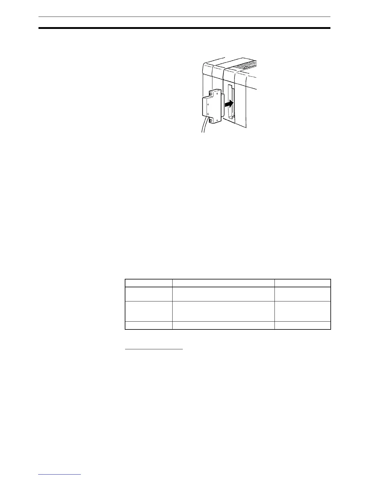
Note When using a cable connector with a locking mechanism, check that the lock
is secure before use.
Prepare a cable for use with connector-type I/O Units (32-point Input or Out-
put Units) in one of the following ways:
• Prepare a cable using a soldered-type socket and a connector cover (pro-
vided as accessories).
• Prepare a cable using a crimp-type or pressure-welded-type socket and a
connector cover (purchased separately).
• Use an OMRON Terminal Block Conversion Unit dedicated cable or an I/
O relay terminal connector cable.
4-7-4 Preparing Cables for 32-point Input and Output Units
Prepare cables for connectors on 32-point Input and Output I/O Units (CQM1-
ID112, CQM1-ID213, CQM1-ID214 and CQM1-OD213, CQM1-OD216) as
explained below.
Recommended
Connectors (Cable Side)
A soldered-type socket and connector cover are provided with each I/O Unit.
Recommended Wire
Use AWG26 to 24 (0.2 to 0.13 mm
2
) wire for connecting to all of the connector
pins.
Note For details on pin arrangement and the internal circuitry of connectors at the
CQM1H side, refer to the sections on DC Input Units (32 points) and Transis-
tor Output Units (32 points) in this manual.
Connector Position
Connector type Model (by Fujitsu) Set (from OMRON)
Soldered Socket: FCN-361J040-AU
Connector cover: FCN-360C040-J2
C500-CE404
Crimp Housing: FCN-363J040
Contact: FCN-363J-AU
Connector cover: FCN-360C040-J2
C500-CE405
Pressure welded FCN-367J040-AU/F C500-CE403

 Loading...


