206
Pulse I/O Board Section 8-2
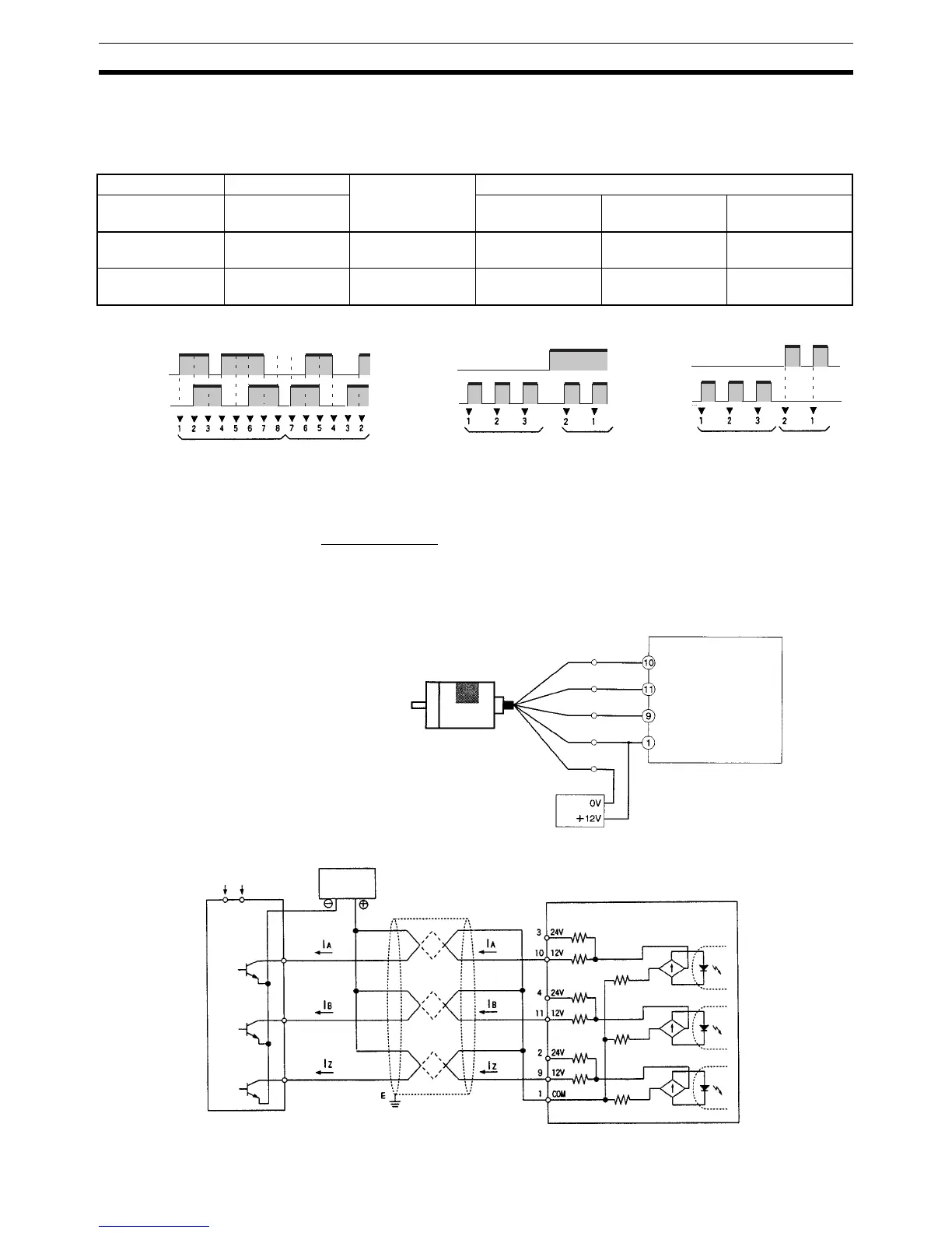
8-2-7 Wiring Examples
Pulse Input Connections Connect the encoder output to CN1 and CN2 as shown below according to
the port Input Mode.
Note The function of encoder inputs A and B in Pulse/Direction Mode and Up/Down
Mode differs from the High-speed Counter Board (CQM1H-CTB41).
Wiring Example
The example below shows connections to an encoder with phases A, B, and
Z.
CN1 pins CN2 pins Signal name Encoder output
Port 1 Port 2 Differential
Phase Mode
Pulse/Direction
Mode
Up/Down Mode
3, 10 3, 10 Encoder input A Encoder Phase A
input
Directional signal
input
Decrement pulse
input
4, 11 4, 11 Encoder input B Encoder Phase B
input
Pulse input Increment pulse
input
Encoder input A
(Phase A)
Encoder Input B
(Phase B)
Differential Phase Mode Up/Down Mode
Encoder input A
(DOWN input)
Encoder input B
(UP input)
Pulse/Direction Mode
Encoder input A
(Direction input)
Encoder input B
(Pulse input)
Decrement
Increment
DecrementIncrement DecrementIncrement
Pulse I/O Board
10 (Encoder input A:
12 V DC)
Pin No.
(Differential Phase Mode)
Encoder
(Power supply: 12 V DC)
Ex: E6B2-CWZ6C
NPN Open-collector output
Black: Phase A
12-V DC power supply
Orange: Phase Z
White: Phase B
Blue: 0 V
(COM)
Brown: +Vcc
1 (Common input
COM)
11 (Encoder input B:
12 V DC)
9 (Pulse input Z:
12 V DC)
Power supply
Encoder
Pulse I/O Board
Shielded twisted-pair cable
(Do not share the power supply with other I/O.)
12-V DC power supply
Phase A
Encoder
output
12 V DC
0 V DC
Phase B
Phase C

 Loading...


