207
Pulse I/O Board Section 8-2
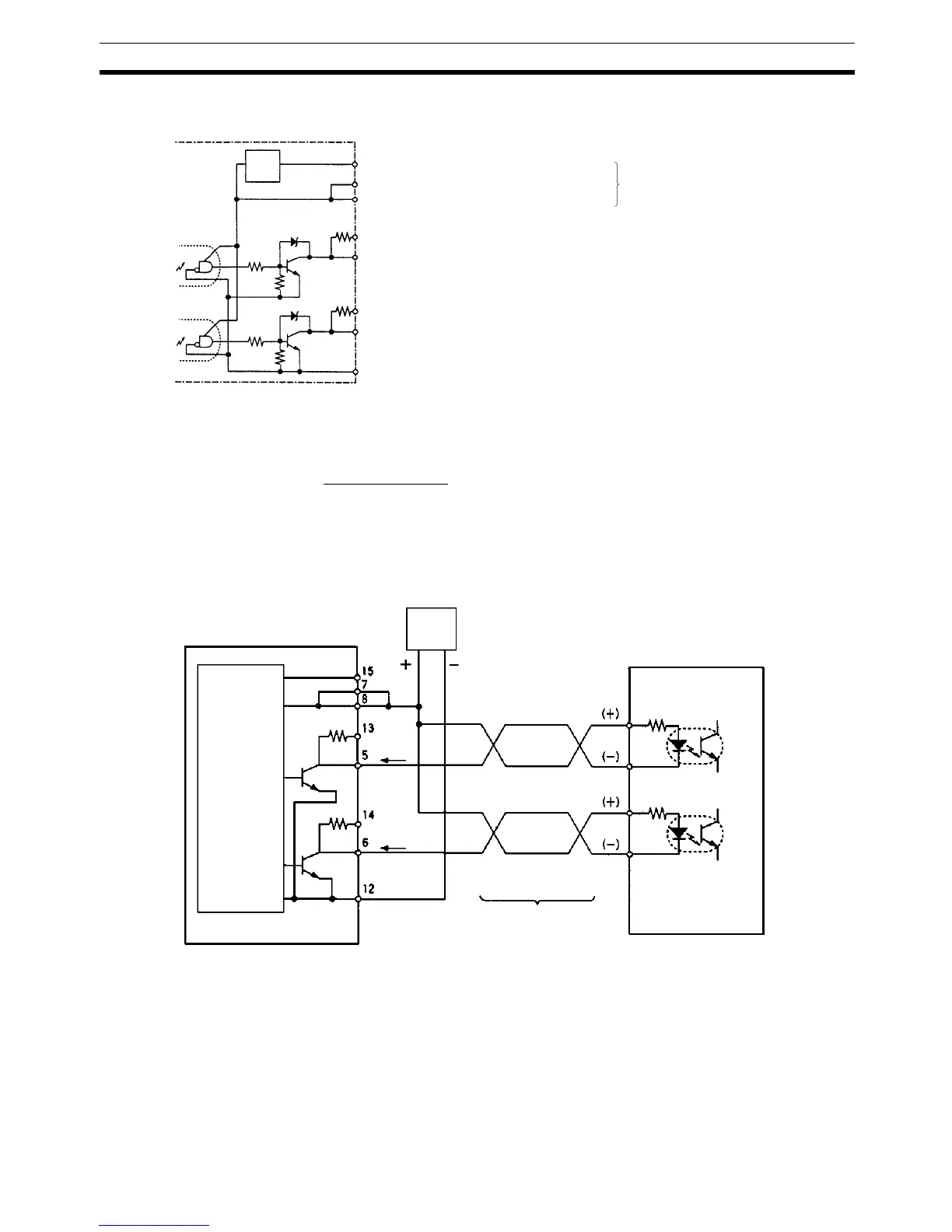
Pulse Output Connections
!Caution Do not supply both 5-V and 24-V DC power at the same time. Doing so will
damage the internal circuits.
Wiring Examples
The following examples show a Pulse I/O Board connected to a motor driver
with a 5-V input.
Example 1: 5-V DC Power Supply
Pulse I/O Board
Low voltage circuit
Pin No.
Supply either 5-V or 24-V power.
Do not supply both at the same
time. (See caution below.)
15 24-V DC power supply for output
13 CCW pulse output (with 1.6 kΩ resistance.)
7 5-V DC power supply for output
8 5-V DC power supply for output
5 CCW pulse output
14 CW pulse output/PWM(––) output (with 1.6 kΩ resistance)
6 CW pulse output/PWM(––) output
12 Common output (0 V)
1.6 kΩ
(1/2 W)
1.6 kΩ
(1/2 W)
Pulse I/O Board
24-V DC
input
5-V DC
input
Approx.
15 mA
Approx.
15 mA
5-V DC power supply
Motor driver (for 5 V input)
Ex: R=220 Ω
CCW
input
(Do not share the power supply with other I/O.)
Shielded twisted-pair cable
CW
input
1.6 kΩ
1.6 kΩ
CCW pulse
output
CW pulse
output

 Loading...


