222
Analog I/O Board Section 8-5
8-5 Analog I/O Board
8-5-1 Model
8-5-2 Function
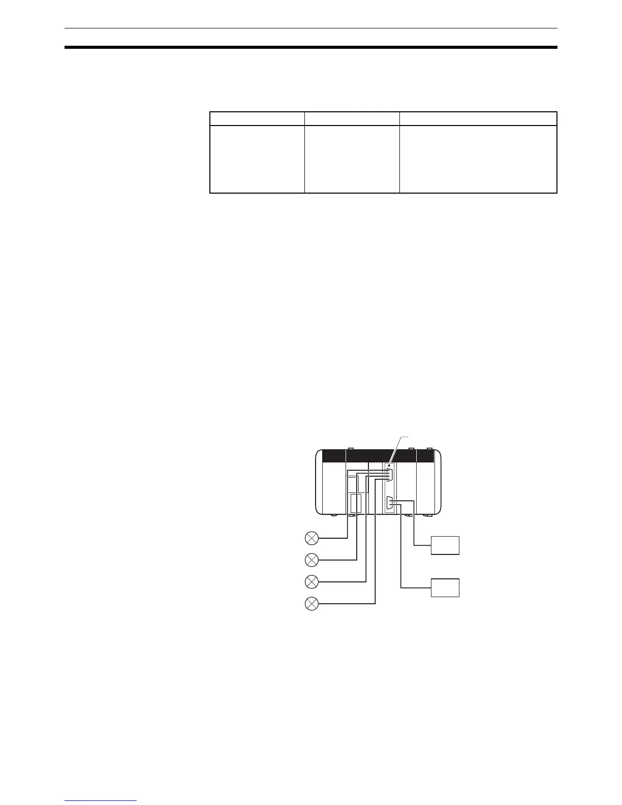
The Analog I/O Board is an Inner Board featuring four analog inputs and two
analog outputs.
The signal ranges that can be used for each of the four analog input points are
–10 to +10 V, 0 to 5 V, and 0 to 20 mA. A separate range is set for each point.
The settings in DM 6611 determine the signal ranges.
The signal ranges that can be used for each of the two analog output points
are –10 to +10 V and 0 to 20 mA. A separate signal range can be selected for
each point. Either a voltage output or current output is selected using the ter-
minal (pins) connected on the connector.
Note Analog Input Averaging Function
The Analog I/O Board does not provide an averaging function such as the one
provided by the CQM1-AD041. If data averaging is required, use the AVG
(AVERAGE) instruction in the CPU Unit program.
8-5-3 System Configuration
Name Model Specifications
Analog I/O Board CQM1H-MAB42 4 analog inputs (–10 to +10 V; 0 to
5 V; 0 to 20 mA; separate signal
range for each point)
2 analog outputs (–10 to +10 V; 0 to
20 mA; separate signal range for
each point)
Analog I/O Board
Four analo

 Loading...


