112
Inner Board Installation Section 4-5
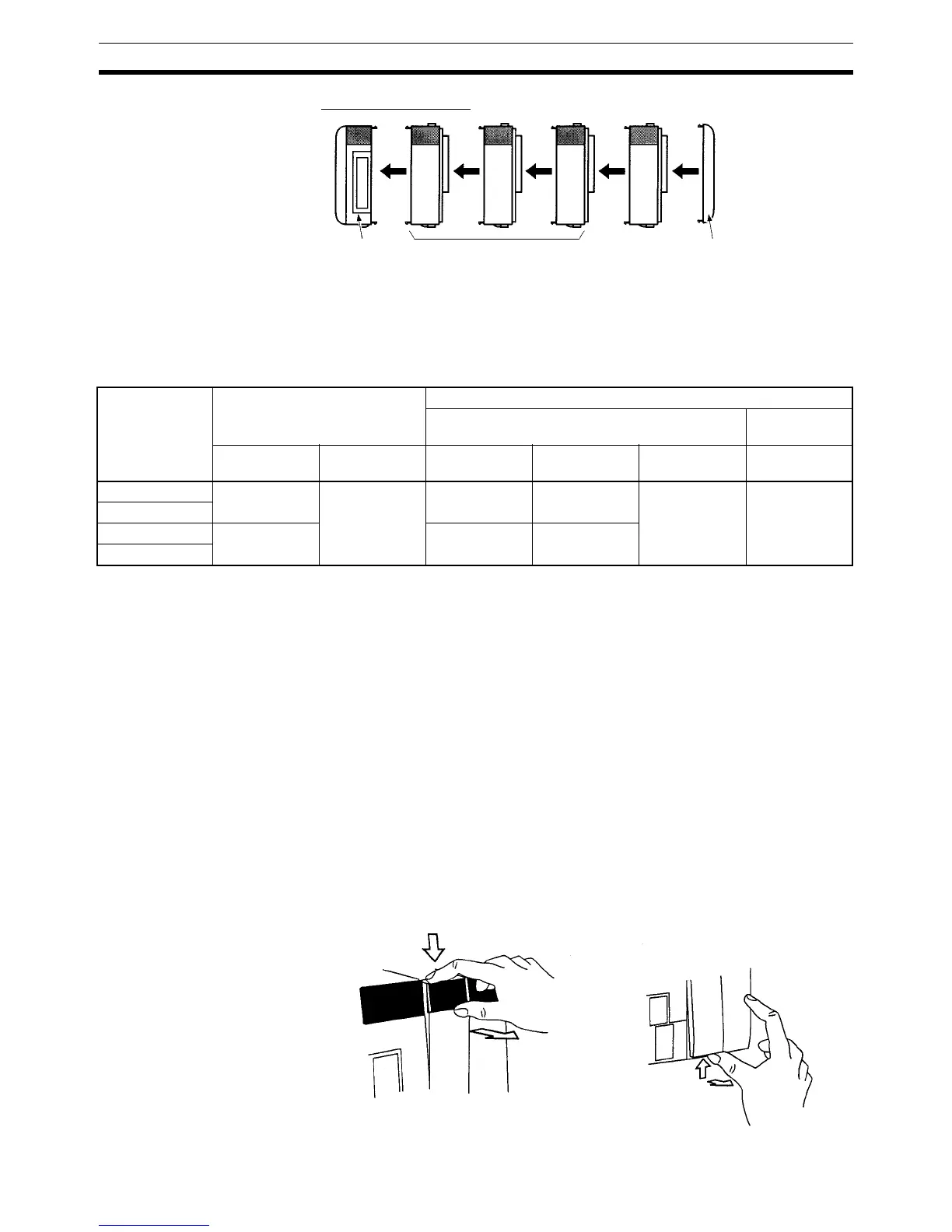
Expansion I/O Block
There is no Backplane for the CQM1H. The PC is constructed by connecting
Units together using the connectors on the sides.
!Caution Attach the End Cover to the Unit on the far right side of the PC. The PC will
not operate properly if the End Cover is not connected.
Note 1. The connected Units (CPU Unit, Communications Unit, Inner Boards, I/O
Units, and Dedicated I/O Units) must be selected so that the maximum cur-
rent capacity of the Power Supply Unit is not exceeded.
2. The connected Units (CPU Unit, Communications Unit, Inner Boards, I/O
Units, Dedicated I/O Units, and I/O Control Unit) must be selected so that
the current consumption does not exceed 3.0 A.
3. The connected Units (I/O Interface Unit, I/O Units, and Dedicated I/O
Units) must be selected so that the current consumption does not exceed
2.0 A
4. The combined current consumption of the CPU Block and the Expansion
I/O Block must not exceed 5 A.
5. An Analog Power Supply Unit must be counted as a Unit, just like the I/O
and Dedicated I/O Units.
4-5 Inner Board Installation
Use the following procedure to mount Inner Boards in the CPU Unit.
1,2,3... 1. Press the catch at the top of the Inner Board compartment cover.
End Cover
(Provided as accessory
with I/O Interface Unit.)
I/O Inter-
face Unit
I/O Units or Dedicated
I/O Units
(11 Unit max.)
CPU Unit CPU Block Only CPU Block and Expansion I/O Block
CPU Block Expansion I/O
Block
Communica-
tions Unit
I/O and Dedi-
cated I/O Units
Communica-
tions Unit
Inner Boards I/O and Dedi-
cated I/O Units
I/O and Dedi-
cated I/O Units
CQM1H-CPU61 1 11 max. (See
note 1.)
1 2 max. 5 max. (See
note 2.)
11 max. (See
note 3.)
CQM1H-CPU51
CQM1H-CPU21 Cannot be
connected.
Cannot be
connected.
Cannot be
mounted.
CQM1H-CPU11
Press the top catch. Press the bottom catch.

 Loading...


