111
Connecting PC Components Section 4-4
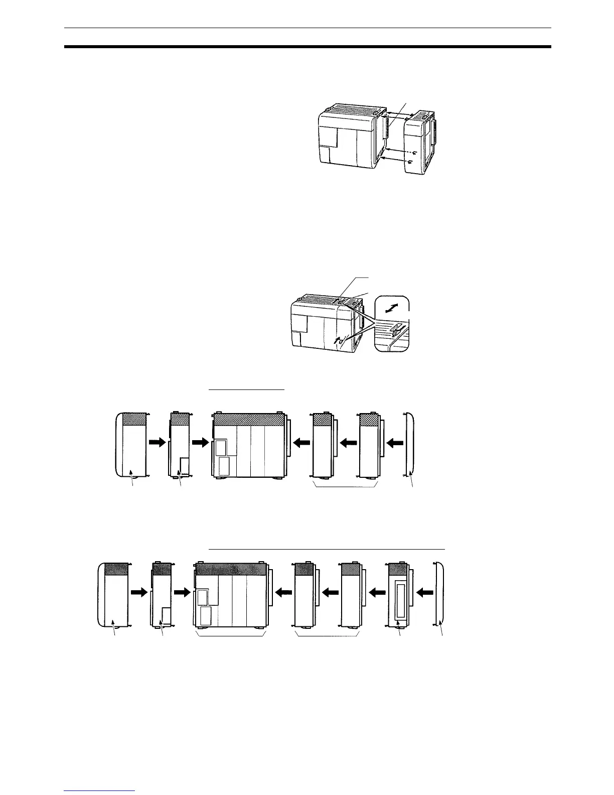
1,2,3... 1. The following diagram shows the connection of two Units that make up a
CQM1H PC. Join the Units so that the connectors fit exactly.
2. The yellow locking tabs at the top and bottom of each Unit lock the Units
together. Slide these locking tabs towards the back of the Units as shown
below until they click into place.
Note If the locking tabs are not secured properly, the CQM1H may not
function properly. Be sure to slide the locking tabs until they are se-
curely in place.
3. Attach the End Cover to the Unit on the far right side of the PC.
CPU Block Only
CPU Block for Connection to Expansion I/O Block
Connector
Lock
Release
Slider
Slide the locking tabs until
they click into place.
End Cover
(Provided as accessory
with CPU Unit.)
Power
Supply
Unit
CPU Unit
Communications Unit
(If required. Sup-
ported only by
CPU51/61 CPU Unit.)
I/O Units or
Dedicated I/O
Units
(11 Unit max.)
End Cover
(Provided as accessory
with CPU Unit.)
Power
Supply
Unit
I/O Units or
Dedicated I/O
Units
(5 Units max.)
Communications Unit
(If required. Supported
only by CPU51/61
CPU Unit.)
CPU Unit
I/O Control
Unit

 Loading...


