208
Pulse I/O Board Section 8-2
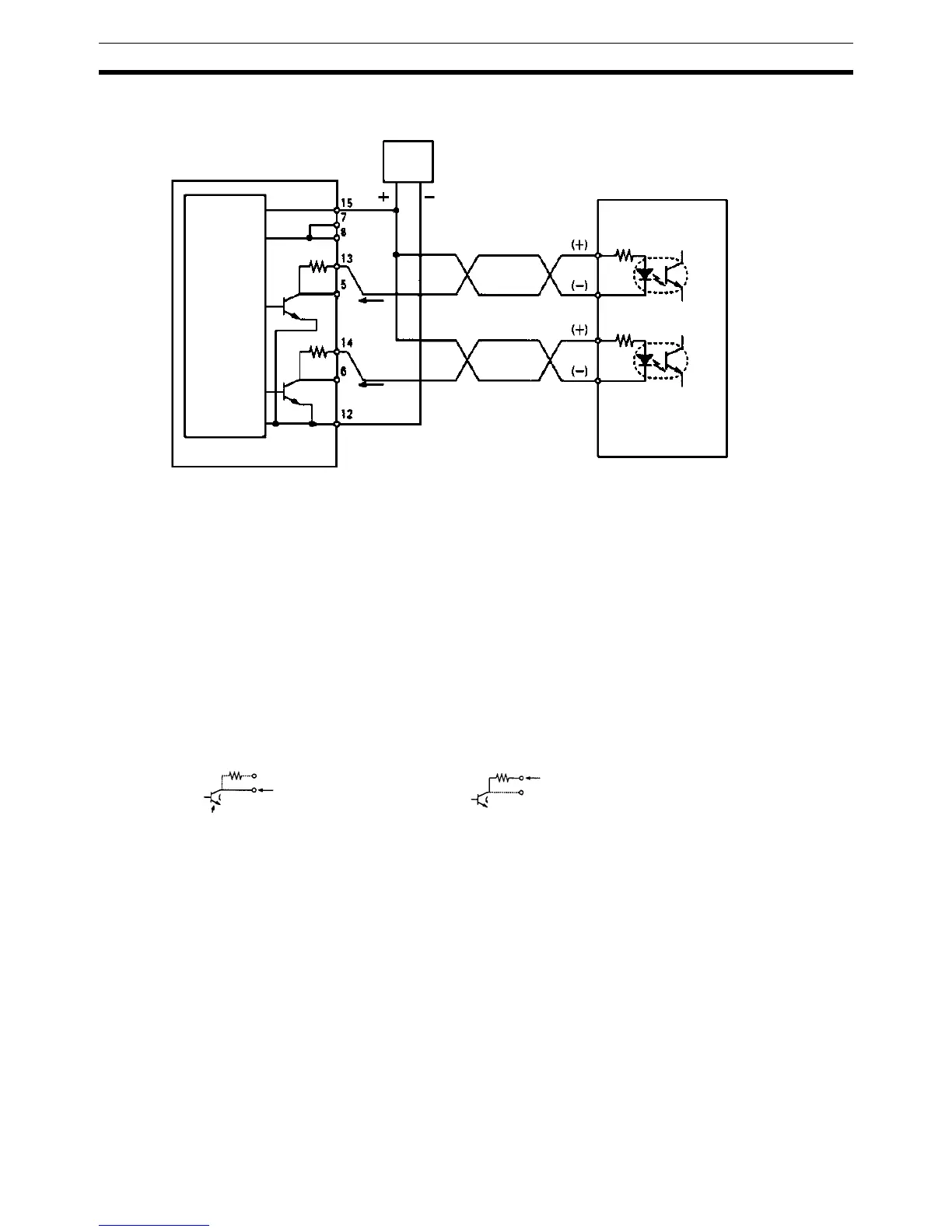
Example 2: 24-V DC Power Supply
!Caution The 5-V DC or 24-V DC power supply for the outputs must be connected cor-
rectly.
Pulse Output Connection
Precautions
• Connect a 7 to 30 mA load to the pulse output. Use a bypass resistor if
the load is smaller than 7 mA.
• The pulse output circuits on pins 13 and 14 have a built-in resistance of
1.6 kΩ (1/2 W). Connect the pulse outputs as shown below according to
the power supply and the motor driver specifications.
Pulse I/O Board
24-V DC
input
Approx.
12 mA
Approx.
12 mA
24-V DC power supply
Motor driver (for 5 V input)
Ex: R=220 Ω
(Do not share the power supply with other I/O.)
Note Here, a 5-V input motor driver is being used with a 24-V
power supply. The internal resistance at the Pulse I/O
Board (1.6 kΩ) is thus used. Care must be taken to avoid
problems caused by the drive current at the motor driver.
1.6 kΩ
1.6 kΩ
5-V DC input
CCW pulse
output
CW pulse
output
Open Collector Output
Output transistor
Output from Open Collector 1.6 k Series Resistance
Output
7 to 30 mA
Output
7 to 30 mA

 Loading...


