126
I/O Unit Wiring Precautions Section 4-8
!Caution Always use crimp connectors for wiring. Do not connect bare stranded wires
directly to terminals.
!Caution To satisfy the EC directives (low-voltage directive), provide reinforced insula-
tion or double insulation on the I/O Units’ DC power supply.
!Caution Install external breakers and take other safety measures against short-circuit-
ing in external wiring. Insufficient safety measures against short-circuiting
may result in burning.
!Caution Double-check all the wiring before turning ON the power supply. Incorrect wir-
ing may result in burning.
!Caution Do not apply voltages exceeding the input voltages to Input Units or voltages
exceeding the switching capacity to Output Units. Doing so may result in dam-
age or destruction of the I/O Unit or result in fire.
Leakage Current
(24 V DC)
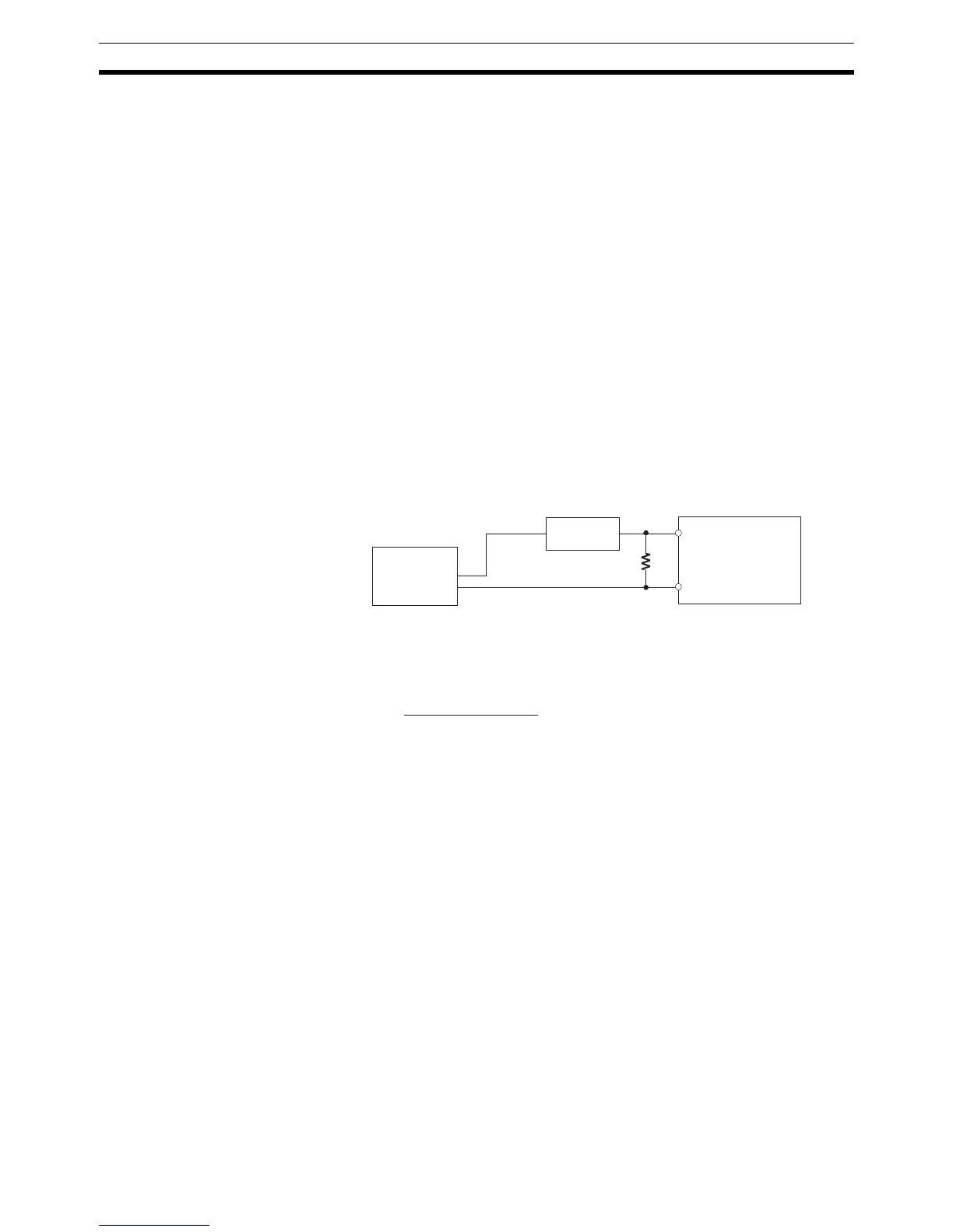
When two-wire sensors, such as photoelectric sensors, proximity sensors, or
limit switches with LEDs, are used, the input bit may be turned ON errone-
ously by leakage current. If the leakage current exceeds 1.3 mA, insert a
bleeder resistor in the circuit to reduce the input impedance, as shown in the
following diagram.
R
CQM1H
Input power
supply
Bleeder resistor
2-wire method
sensor, etc.
R = 7.2/(2.4 I–3) kΩ max.
W = 2.3/R W min.
I: Device's leakage current (mA)
R: Bleeder resistance (kΩ)
W: Bleeder resistor's power rating (W)
The equations above were derived from the following equation:
W ≥ Input volta
ge (24)/R × Input voltage (24) × margin (4)
I ×
R ×
Input voltage (24)
Input current (10)
R +
Input voltage (24)
Input current (10)
≤ OFF voltage (3)

 Loading...


