130
Connecting Programmable Terminals Section 4-10
Use the following cables to connect to the PT. For details, refer to the relevant
operation manual.
Cables for 1:1 Connections between PC and PT
Note For details of connections to the RS-422A/485 port on the Serial Communica-
tions Board, refer to the relevant operation manual.
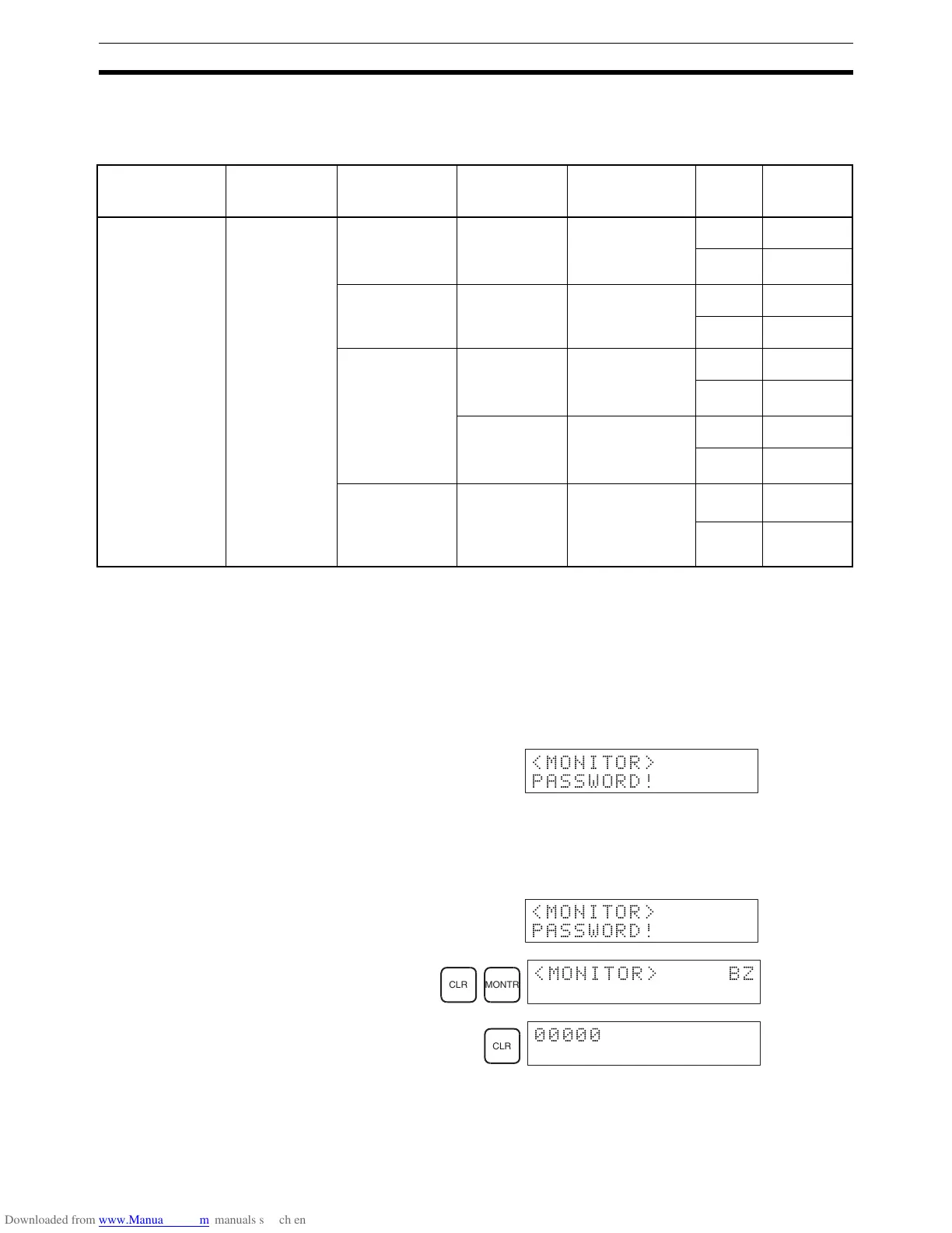
Automatic Mode Change When the PC is in RUN mode with a Programming Console connected to the
peripheral port of the CPU Unit, if a PT is connected to the CPU Unit’s built-in
RS-232C port or either of the ports of a CQM1H-SCB41 using Host Link
mode, the following message will be displayed at the Programming Console
indicating that a password is required to continue operation (using the Pro-
gramming Console).
This is because, in order to write data to the CPU Unit, the PT changed the
operation mode from RUN mode to MONITOR mode. To continue operation
using the Programming Console, it is necessary to input the password again.
Inputting the Password
• The mode will not be changed if the PT is connected via an NT Link.
PC Unit or Board PC port PT PT port Serial
communications
mode (see note)
Length Model
CPU Unit or Serial
Communications
Board
For the CPU Unit,
the mode will be
1:1, for the Serial
Communications
Board, the mode
will be 1:1 or 1:N.
RS-232C port
(D-Sub, 9-pin,
female)
NT20S, NT600S,
NT620S,
NT620C,
NT625C
RS-232C port
(D-Sub, 9-pin,
female)
Host Link or NT
Link (1:1 mode or
1:N mode)
2 m XW2Z-200T
5 m XW2Z-500T
NT30, NT30C RS-232C port
(D-Sub, 9-pin,
female)
Host Link or NT
Link (1:1 mode)
2 m XW2Z-200T
5 m XW2Z-500T
NT31, NT31C,
NT631, NT631C
Por t A:
RS-232C port
(D-Sub, 9-pin,
female)
Host Link or NT
Link (1:1 mode or
1:N mode)
2 m XW2Z-200T
5 m XW2Z-500T
Por t B:
RS-232C port
(D-Sub, 25-pin,
female)
Host Link or NT
Link (1:1 mode or
1:N mode)
2 m XW2Z-200S
5 m XW2Z-500S
NT20M,
NT600M,
NT610G,
NT612G,
NT610C
RS-232C port
(D-Sub, 25-pin,
female)
Host Link 2 m XW2Z-200S
5 m XW2Z-500S
<MONITOR>
PASSWORD!
<MONITOR>
PASSWORD!
CLR MONTR
<MONITOR> BZ
CLR

 Loading...


