xxv
Upgrades Made to New Version of CQM1H CPU Units 7
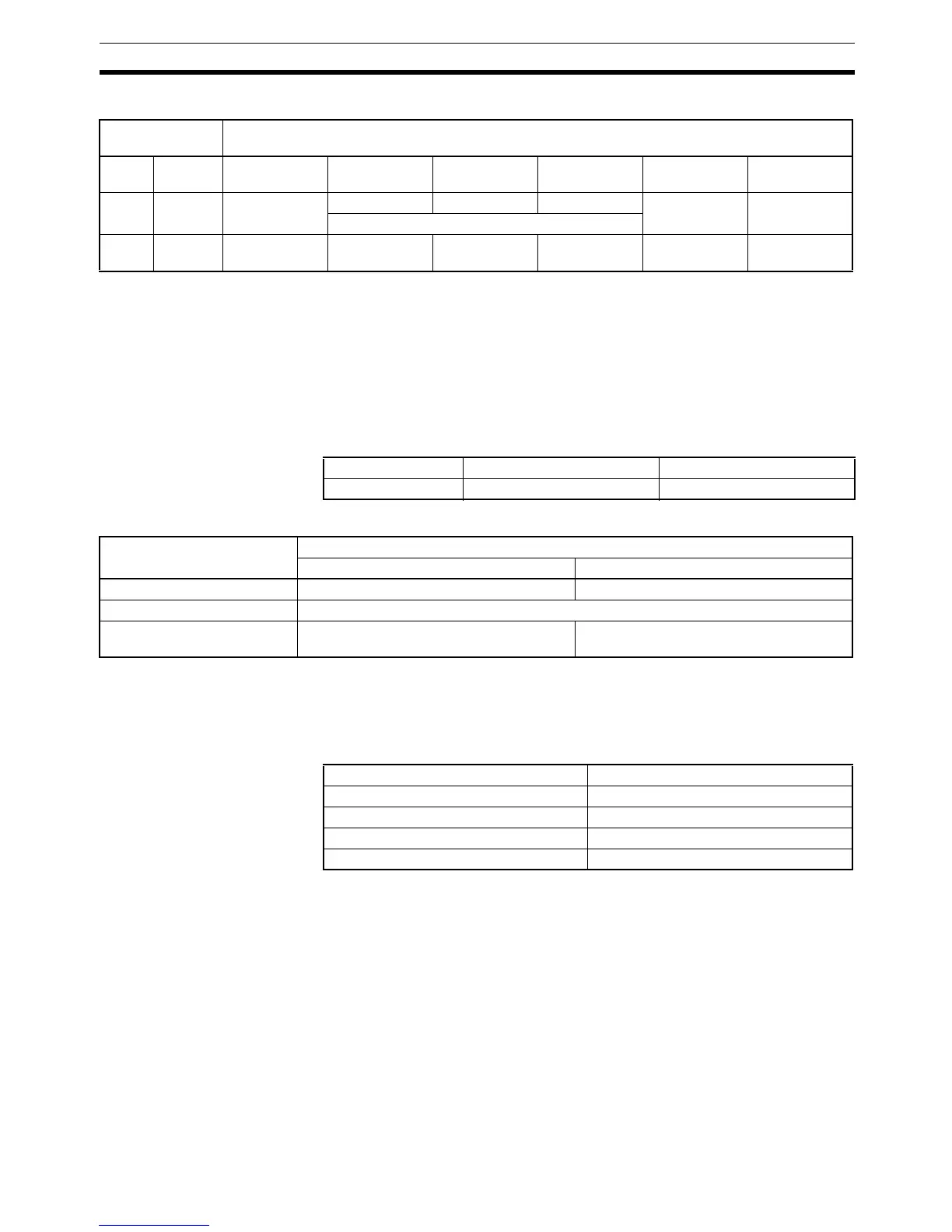
Effect of Pin 5 and Pin 7 on Serial Communications Mode
Note The setting of pin 7 is ignored. Leave it at the factory setting.
Effect of Pin 7 on the Operating Mode at Startup
The effect of the setting of pin 7 on the operating mode at startup is as shown
below following the information provided in Change to Settings of Pin 7 on DIP
Switch on the previous page.
PLC Setup Setting
Operating Mode
Note The following table shows the relationship between the operating mode and
Connecting Cable when a device other than a Programming Console is con-
nected.
Note If the power supply to the CQM1H is cycled after connected online to a per-
sonal computer-based Programming Device, PROGRAM mode will be
entered.
Addition of Special Instruction for Temperature Control Units
The I/O COMMAND TRANSMISSION instruction (IOTC(– –)) has been added
for the CQM1-TC20@/TC30@ Temperature Control Units. Refer to the
CQM1H/CQM1 Series Dedicated I/O Units Operation Manual (W238-E1-09)
for details.
Front panel DIP
switch
Peripheral port
Pin 5 Pin 7 Programming
Console
Peripheral bus Host Link No-protocol 1:1 data link NT Link (1:1
mode)
OFF OFF/ON OK OK OK OK No No
According to PLC Setup
ON OFF/ON OK OK (standard
settings)
OK (standard
settings)
No No No
Address Bits Setting
DM 6600 08 to 15 00 Hex
Connected device at startup Setting of pin 7 on DIP switch
ON OFF
Nothing connected RUN mode PROGRAM mode
Programming Console Mode set on key switch on Programming Console
Device other than Program-
ming Console
PROGRAM or RUN mode depending on
the Connecting Cable (See note.)
PROGRAM mode
Connecting Cable Operating mode at startup
CS1W-CN114 + CQM1-CIF01/02 PROGRAM mode
CS1W-CN118 + XW2Z-200S/500S (-V) PROGRAM mode
CS1W-CN226/626 RUN mode (See note.)
CS1W-CN118 + XW2Z-200S/500S-CV RUN mode (See note.)

 Loading...


