46
Unit Specifications Section 2-1
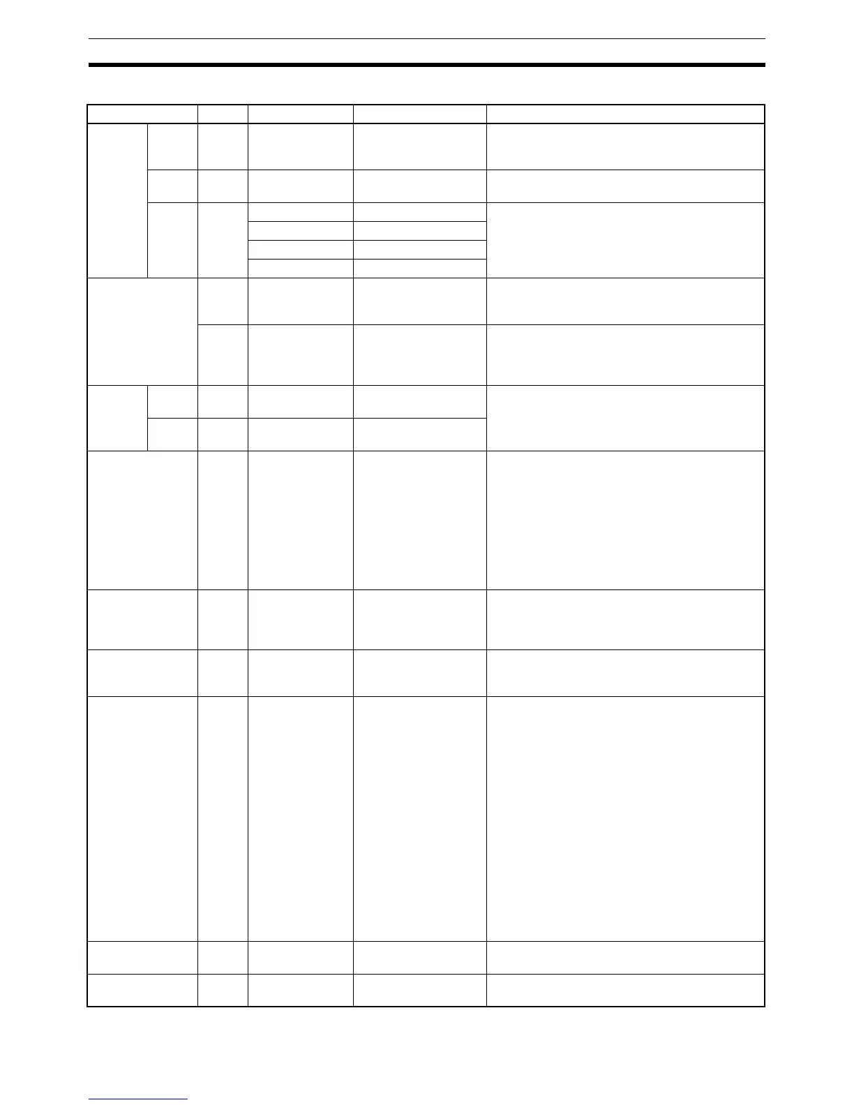
Memory Area Structure
Data area Size Words Bits Function
IR area
(note 1)
Input
area
256
bits
IR 000 to IR 015 IR 00000 to IR 01515 Input bits can be allocated to Input Units or I/O
Units. The 16 bits in IR 000 are always allocated
to the CPU Unit’s built-in inputs.
Output
area
256
bits
IR 100 to IR 115 IR 10000 to IR 11515 Output bits can be allocated to Output Units or
I/O Units.
Work
areas
2,528
bits
min.
(note
2)
IR 016 to IR 089 IR 01600 to IR 08915 Work bits do not have any specific function and
they can be freely used within the program.
IR 116 to IR 189 IR 11600 to IR 18915
IR 216 to IR 219 IR 21600 to IR 21915
IR 224 to IR 229 IR 22400 to IR 22915
Controller Link
status areas
96 bits IR 090 to IR 095 IR 09000 to IR 09515 Used to indicate the Controller Link data link
status information. (Can be used as work bits
when a Controller Link Unit is not connected.)
96 bits IR 190 to IR 195 IR 19000 to IR 19515 Used to indicate the Controller Link error and
network participation information. (Can be used
as work bits when a Controller Link Unit is not
connected.)
MACRO
operand
area
(note 2)
Input
area
64 bits IR 096 to IR 099 IR 09600 to IR 09915 Used when the MACRO instruction, MCRO(99),
is used. (Can be used as work bits when the
MACRO instruction is not used.)
Output
area
64 bits IR 196 to IR 199 IR 19600 to IR 19915
Inner Board slot 1
area
256
bits
IR 200 to IR 215 IR 20000 to IR 21515 These bits are allocated to the Inner Board
mounted in slot 1 of a CQM1H-CPU51/61. (Can
be used as work bits when slot 1 is empty.)
CQM1H-CTB41 High-speed Counter Board:
IR 200 to IR 213 (14 words): Used by the Board
IR 214 and IR 215 (2 words): Not used.
CQM1H-SCB41 Serial Communications Board:
IR 200 to IR 207 (8 words): Used by the Board
IR 208 to IR 215 (8 words): Not used.
Analog settings
area (note 1)
64 bits IR 220 to IR 223 IR 22000 to IR 22315 Used to store the analog settings when a
CQM1H-AVB41 Analog Setting Board is
mounted. (Can be used as work bits when an
Analog Setting Board is not mounted.)
High-speed
Counter 0 PV
(note 1)
32 bits IR 230 to IR 231 IR 23000 to IR 23115 Used to store the present values of high-speed
counter 0. (Can be used as work bits when
high-speed counter 0 is not being used.)
Inner Board slot 2
area
192
bits
IR 232 to IR 243 IR 23200 to IR 24315 These bits are allocated to the Inner Board
mounted in slot 2. (Can be used as work bits
when a CQM1H-CPU11/21 is being used or slot
2 is empty.)
CQM1H-CTB41 High-speed Counter Board:
IR 232 to IR 243 (12 words): Used by the Board
CQM1H-ABB21 Absolute Encoder Interface
Board:
IR 232 to IR 239 (8 words): Used by the Board
IR 240 to IR 243 (4 words): Not used.
CQM1H-PLB21 Pulse I/O Board:
IR 232 to IR 239 (8 words): Used by the Board
IR 240 to IR 243 (4 words): Not used.
CQM1H-MAB42 Analog I/O Board:
IR 232 to IR 239 (8 words): Used by the Board
IR 240 to IR 243 (4 words): Not used.
SR area 184
bits
SR 244 to
SR 255
SR 24400 to
SR 25515
These bits serve specific functions such as flags
and control bits.
HR area 1,600
bits
HR 00 to HR 99 HR 0000 to HR 9915 These bits store data and retain their ON/OFF
status when power is turned off.

 Loading...


