51
Input Unit Specifications Section 2-2
IR 00000 to IR 00015 are always allocated to the CPU Unit’s 16 built-in input
points.
• Inputs IN0 to IN 3 (corresponding to IR 00000 to IR 00003) can be set in
the PC Setup to be used as input interrupts.
• Inputs IN4 to IN7 (corresponding to IR 00004 to 00007) can be used as
high-speed counter 0.
Note If IN0 through IN3 are set for use as input interrupts in the PC Setup, the ON
and OFF delays for input interrupts are fixed at 0.1 ms max. and 0.5 ms max.,
respectively. If IN4 through IN6 are set for use as high-speed counter inter-
rupts, the delays for high-speed counters are as shown in the following table.
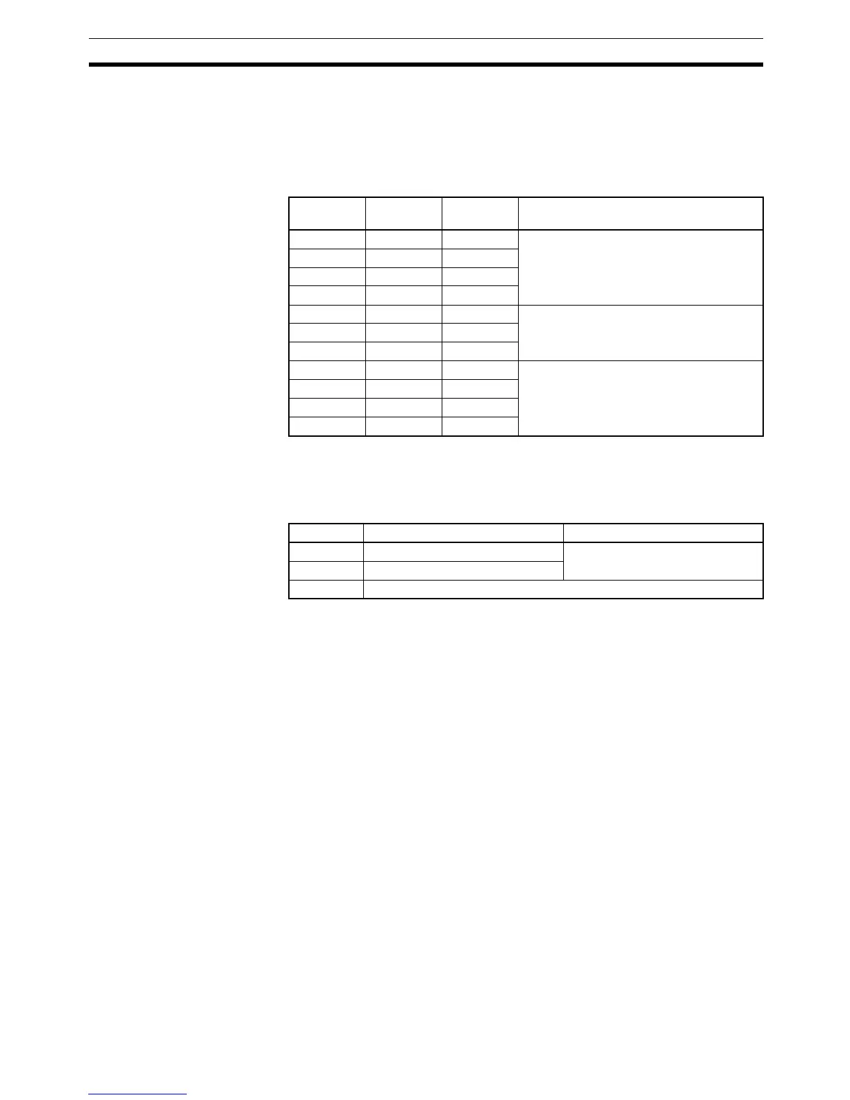
Terminal Input
number
Input bit Function
B0 IN0 IR 00000 Normal inputs or input interrupts (Input
Interrupt Mode or Counter Mode): set in
PC Setup (DM 6628).
A0 IN1 IR 00001
B1 IN2 IR 00002
A1 IN3 IR 00003
B2 IN4 IR 00004 Normal inputs or high-speed counter 0:
set in PC Setup (DM 6642).
A2 IN5 IR 00005
B3 IN6 IR 00006
A3 IN7 IR 00007 Only usable as normal inputs.
to to to
B7 IN14 IR 00014
A7 IN15 IR 00015
Input Incrementing mode Differential phase mode
IN4 (A) 5 kHz 2.5 kHz
IN5 (B) Normal input
IN6 (Z) ON: 100 µs min. required; OFF delay: 500 µs min. required

 Loading...


