Controlling/Outputting in Parallel
102
FQ-CR2 User’s Manual
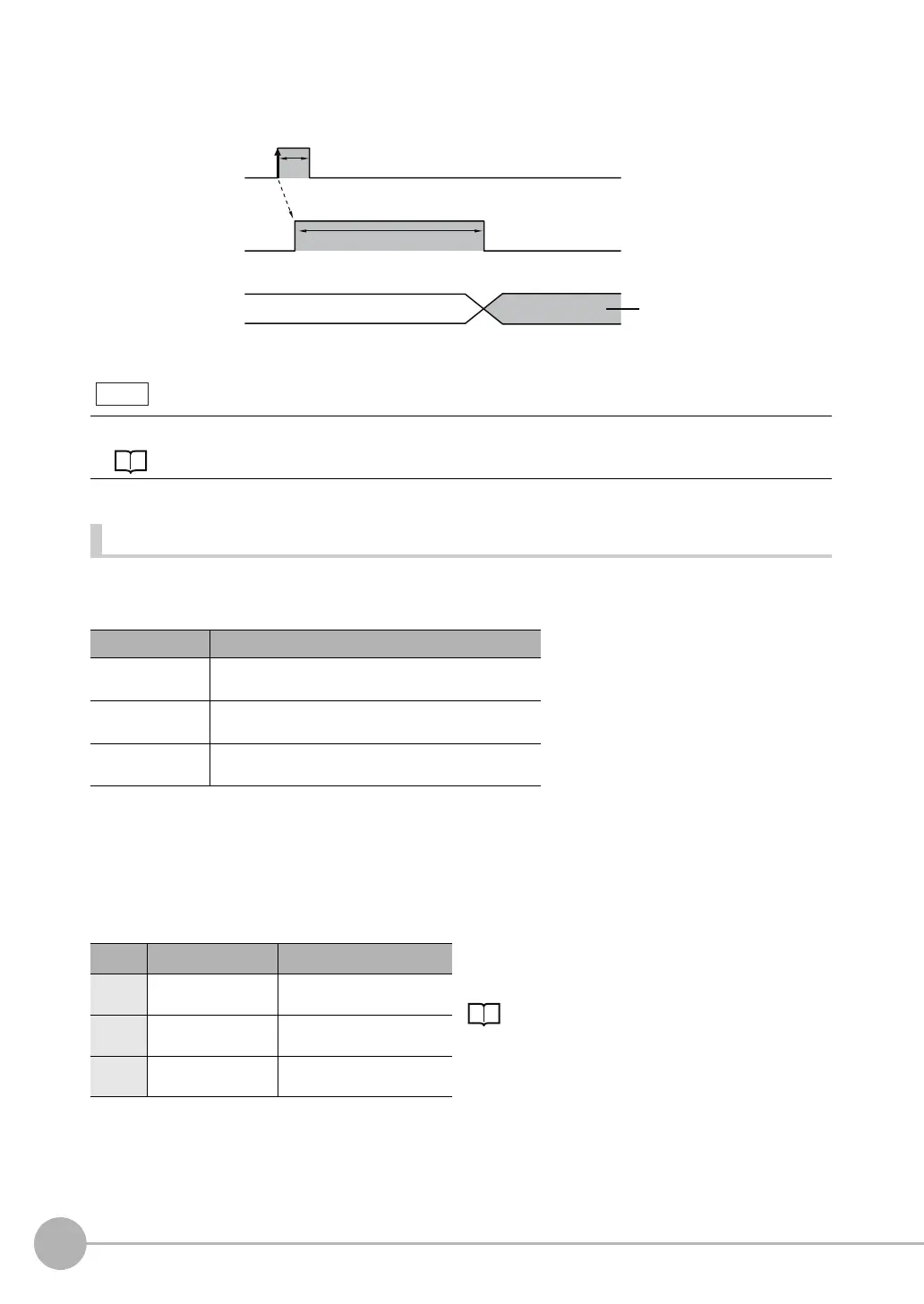
Timing Chart
The OR signal that is output is held until the next overall judgement is output.
Obtaining Individual Judgement Results
Up to three judgement results of individual inspection items (individual judgement signals OR0 to OR31) can
be assigned to terminals OUT0 to OUT2 and output to external devices.
Wiring
Example: Signals are assigned to terminals OUT0 to OUT2 as shown below.
• OUT0: Inspection number 2 (OR2)
• OUT1: Inspection number 5 (OR5)
• OUT2: Inspection number 14 (OR14)
As described above, if terminals OUT0 to OUT2 are all assigned to individual judgement output signals, the
BUSY signal and ERROR signal assigned as the default settings will no longer be output.
The timing for updating the OR signal and the ON time after judgement processing can be adjusted.
Adjusting the judgement output timing: p. 104
Output terminal Output signals that can be assigned
OUT0 • OR (Total judgement)...(default)
• OR0 (Item 0 judgement) to OR31 (Item 31 judgement)
OUT1 • BUSY (default)
• OR0 (Item 0 judgement) to OR31 (Item 31 judgement)
OUT2 • ERROR (default)
• OR0 (Item 0 judgement) to OR31 (Item 31 judgement)
Color Signal Description
The signals shown at the left are used.
Refer to the following information for signal wiring.
2-4 Wiring: p. 26
Black OUT0 (OR2) Outputs the judgement for
OR2.
Orange OUT1 (OR5) Outputs the judgement for
OR5.
Light
blue
OUT2 (OR14) Outputs the judgement for
OR14.
OFF
ON
OFF
ON
Overall judgement
Turned ON when overall
judgement is NG.
(Output polarity: ON for NG)
OR signal
ON while measurements are
being processed (depends
on BUSY output conditions)
BUSY signal
TRIG signal
ON for 1 ms min.
FQ Sensor User Manual.book 102 ページ 2011年7月8日 金曜日 午後2時30分